
Sound effect producing apparatus for vehicle

a technology for producing equipment and sound effects, applied in the direction of electric devices, amplification control, transmission, etc., can solve the problem that the gap may seem strange to the driver

Active Publication Date: 2011-11-15
HONDA MOTOR CO LTD
View PDF14 Cites 5 Cited by
  • Summary
  • Abstract
  • Description
  • Claims
  • Application Information

AI Technical Summary

Benefits of technology

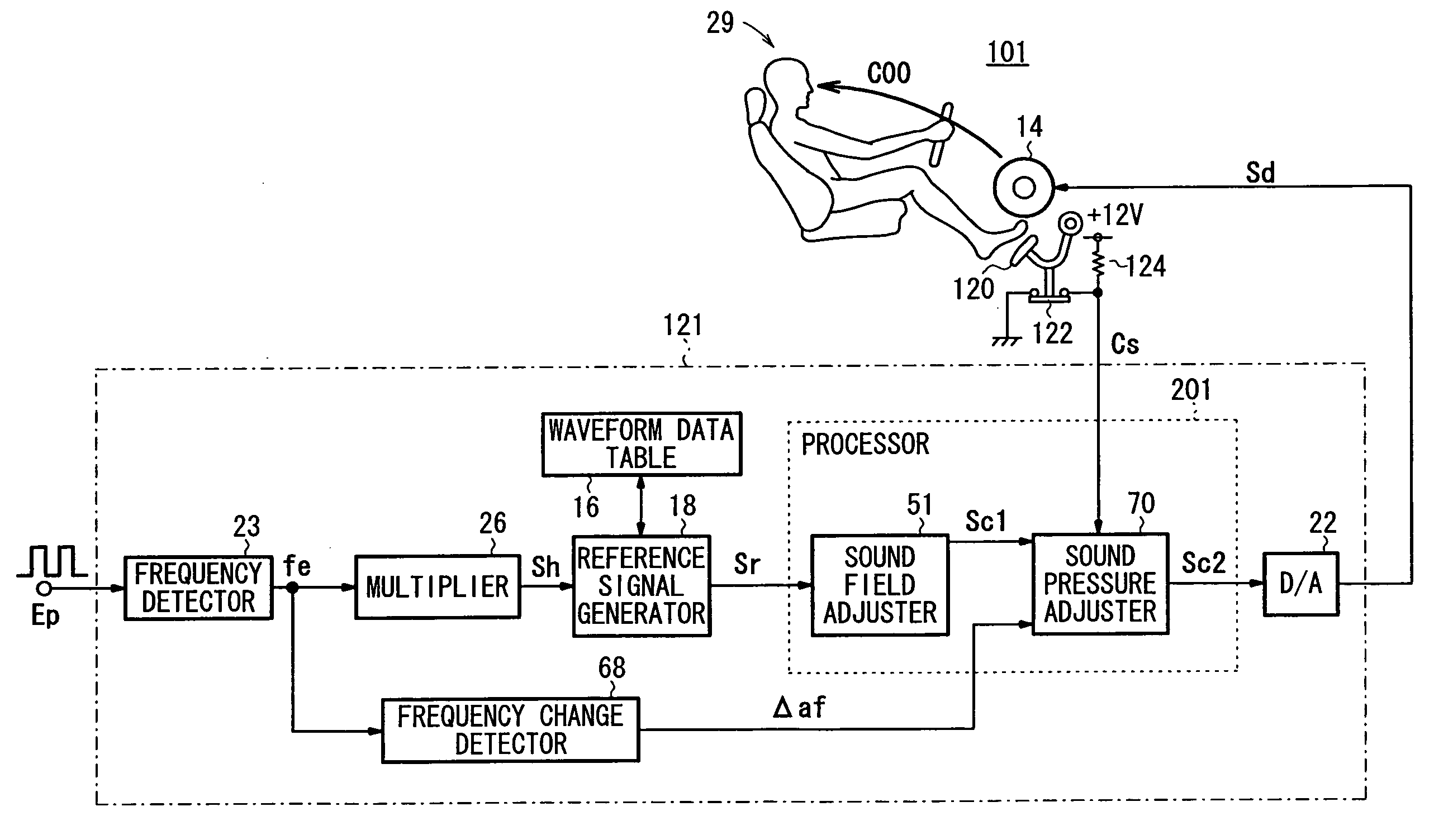
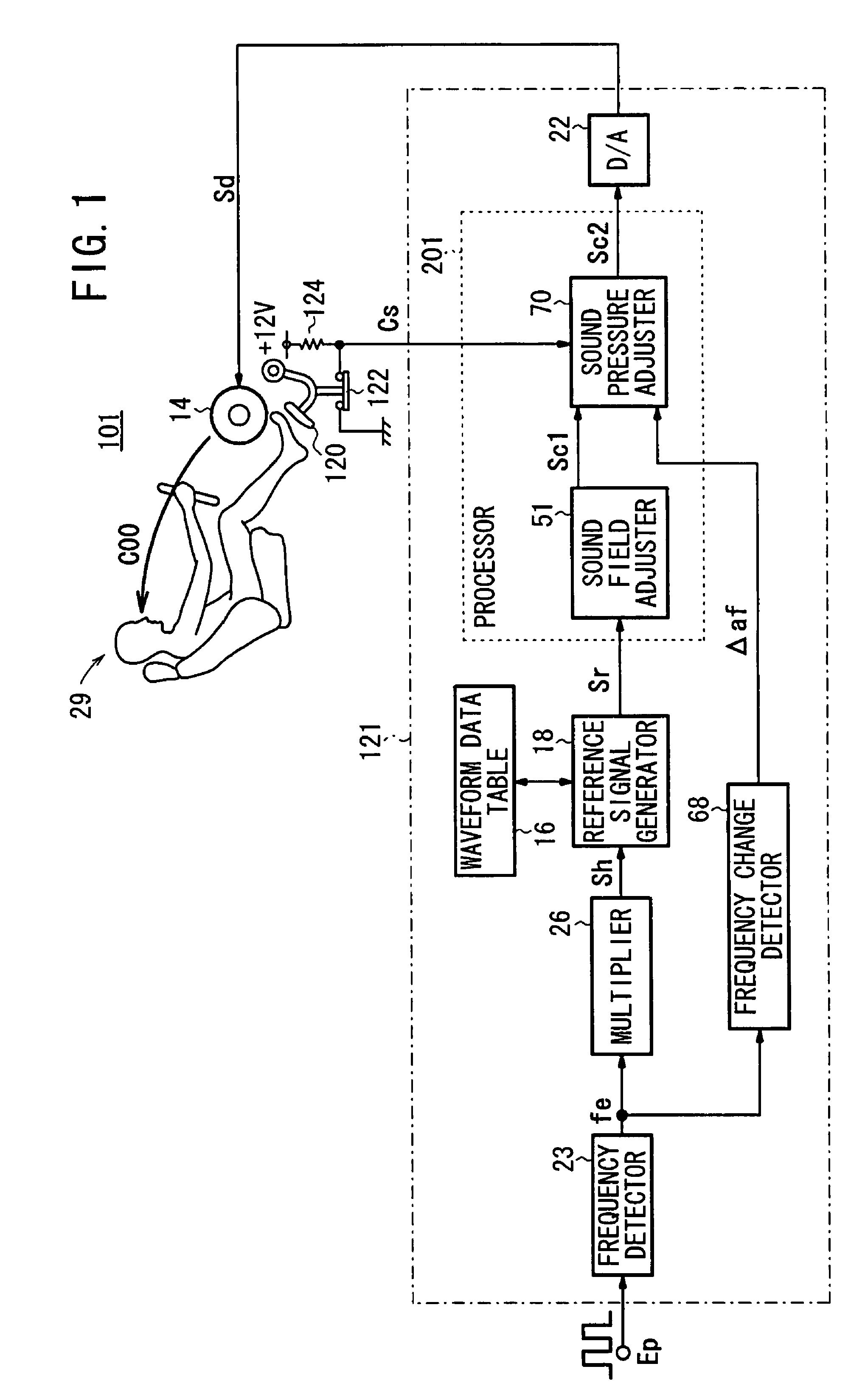
The present invention provides a sound effect producing apparatus for a vehicle that can produce a natural sound effect during downshifting and heel-and-toe operations. The apparatus includes a waveform data table for storing waveform data, a frequency detector for detecting the engine rotational frequency, a reference signal generator for generating a harmonic reference signal, an output means for converting the control signal into the sound effect, and a clutch signal generator for generating a clutch signal indicating the engagement state of the clutch. The apparatus uses a processor to generate a control signal based on the sound source information, such as vehicle driving state information or engine operation information. The control signal is then converted into the sound effect and outputted through the vehicle's sound system. The clutch signal generator generates the clutch signal based on the pressed state of the clutch pedal. The apparatus also includes a normal gain table and a shift-change gain table for different driving situations. The sound effect producing apparatus provides a more natural sound effect during downshifting and heel-and-toe operations.

Problems solved by technology

Such a gap may seem strange to the driver or to a passenger riding in the vehicle.
However, when the heel-and-toe operation is performed, the above operations are performed only for a very short period of time, e.g., for 1 to 2 seconds.

Method used


Image

  • Sound effect producing apparatus for vehicle
  • Sound effect producing apparatus for vehicle
  • Sound effect producing apparatus for vehicle

Examples


second embodiment

B. Second Embodiment

1. Summary of Mechanism for Producing Sound Effect

first embodiment

(Difference Relative to First Embodiment)]

[0122]FIG. 13 shows a block diagram of a sound effect producing apparatus 101A for a vehicle according to a second embodiment of the present invention.

[0123]The sound effect producing apparatus 101A has an arrangement similar to that of the sound effect producing apparatus 101 shown in FIG. 1. However, the apparatus 101A also includes a velocimeter 30 for detecting a velocity v [m / s] of the vehicle, along with an acceleration calculator 32 for calculating vehicle acceleration Δav [m / s2] based on the velocity v. Further, the apparatus 101A does not include the multiplier 26. The velocity v detected by the velocimeter 30 is output to the reference signal generator 18 and to the acceleration calculator 32. The acceleration Δav calculated by the acceleration calculator 32 is output to the sound pressure adjuster 70 of the processor 201. The engine rotational frequency fe from the frequency detector23 is output only to the frequency change detect...


PUM


Abstract

A processor determines an engagement state of a clutch based on a clutch signal, which is output from a clutch switch connected to a clutch pedal. In a declutching state, the processor lowers weighting gain characteristics that serve as acoustic correcting characteristics used in a sound pressure adjuster. Therefore, even when a change of an engine rotational frequency per unit of time increases during a shift-change operation, the gain of the control signal is prevented from increasing. Accordingly, a gap between real acceleration of the vehicle and a sound effect output from a speaker can be decreased, thereby reducing the possibility that the driver and / or a passenger in the vehicle may feel a sense of strangeness relative to the sound effect.

Description

CROSS-REFERENCE TO RELATED APPLICATION[0001]This application claims the priority of JP Application No. 2006-083772, filed Mar. 24, 2006 and JP Application No. 2006-083796, filed Mar. 24, 2006, the entire specification, claims and drawings of which are incorporated herewith by reference.BACKGROUND OF THE INVENTION[0002]1. Field of the Invention[0003]The present invention relates to an apparatus for producing a sound effect in a vehicle, depending on sound source information, including vehicle driving state information or engine operation information.[0004]2. Description of the Related Art[0005]Heretofore, there have been proposed in the art a sound effect producing apparatus for detecting accelerating or decelerating actions made by a driver, and producing and radiating a sound effect into the vehicle cabin, depending on the acceleration or deceleration of the vehicle, by means of a speaker installed in the vehicle cabin, as disclosed in Japanese Laid-Open Patent Publication No. 54-8...

Claims


Application Information

Patent Timeline
Patent Type & Authority Patents(United States)
IPC IPC(8): H04B1/00H03G3/20H03G3/00
CPCB60W50/14
Inventor KOBAYASHI, YASUNORIINOUE, TOSHIOTAKAHASHI, AKIRASAKAMOTO, KOSUKE
Owner HONDA MOTOR CO LTD
Learn More