
Rechargeable battery assembly with movable connector and power conversion circuitry

a technology of power conversion circuit and rechargeable batteries, which is applied in the direction of cell components, cell component details, safety/protection circuits, etc., can solve the problems of limiting the overall “portability” of rechargeable batteries, inconvenience for consumers to carry dedicated chargers and cables for each of their appliances, and reducing self-discharge. , the effect of preventing excessive current draw

Active Publication Date: 2011-11-15
MOIXA ENERGY HLDG
View PDF28 Cites 14 Cited by
  • Summary
  • Abstract
  • Description
  • Claims
  • Application Information

AI Technical Summary

Benefits of technology

"The invention provides a rechargeable battery assembly with a built-in connector that can be mechanically reversed between a deployed configuration and a charge configuration. The battery assembly can be charged by a conventional external charger device or a powered receptacle on a computing or peripheral device. The battery assembly can provide a discharge to at least one voltage level and can be powered by a variety of rechargeable chemistries. The connector can be reduced in size or folded, slid, rotated, or flexed for storage when not in use. The battery assembly has a cap that can make electrical contact with an external device or be charged by a suitable external charger. The cap can also have a secondary prong for additional electrical contact. The battery assembly can use a step-down circuit or a MOSFET buck-boost converter for power conversion. The charging can be controlled using a resistor or a controller chip that manages charging modes such as linear charging, trickle charging, timed charging, or high current charging in short bursts."

Problems solved by technology

A significant problem with rechargeable batteries is their general dependency on an external recharging unit, plug and AC socket.
This limits the overall “portability” of rechargeable batteries as there is a need to find and carry a charger and connect it to an AC mains supply (which is also less suitable for children due to safety concerns related to high voltages).
A further problem is the proliferation of chargers for different battery chemistries creating potential confusion as well as safety concerns, as charging cells in the wrong charger or in an old charger can create problems.
Consumers are also inconvenienced by carrying dedicated chargers and cables for each of their appliances.
The present arrangements encourage a proliferation of chargers, as well as a disposable battery culture where in excess of 15 billion batteries are thrown away annually, creating a significant environmental and waste problem.

Method used


Image

  • Rechargeable battery assembly with movable connector and power conversion circuitry
  • Rechargeable battery assembly with movable connector and power conversion circuitry
  • Rechargeable battery assembly with movable connector and power conversion circuitry

Examples


Embodiment Construction

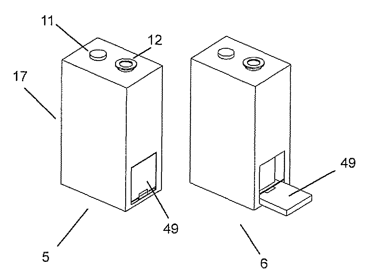
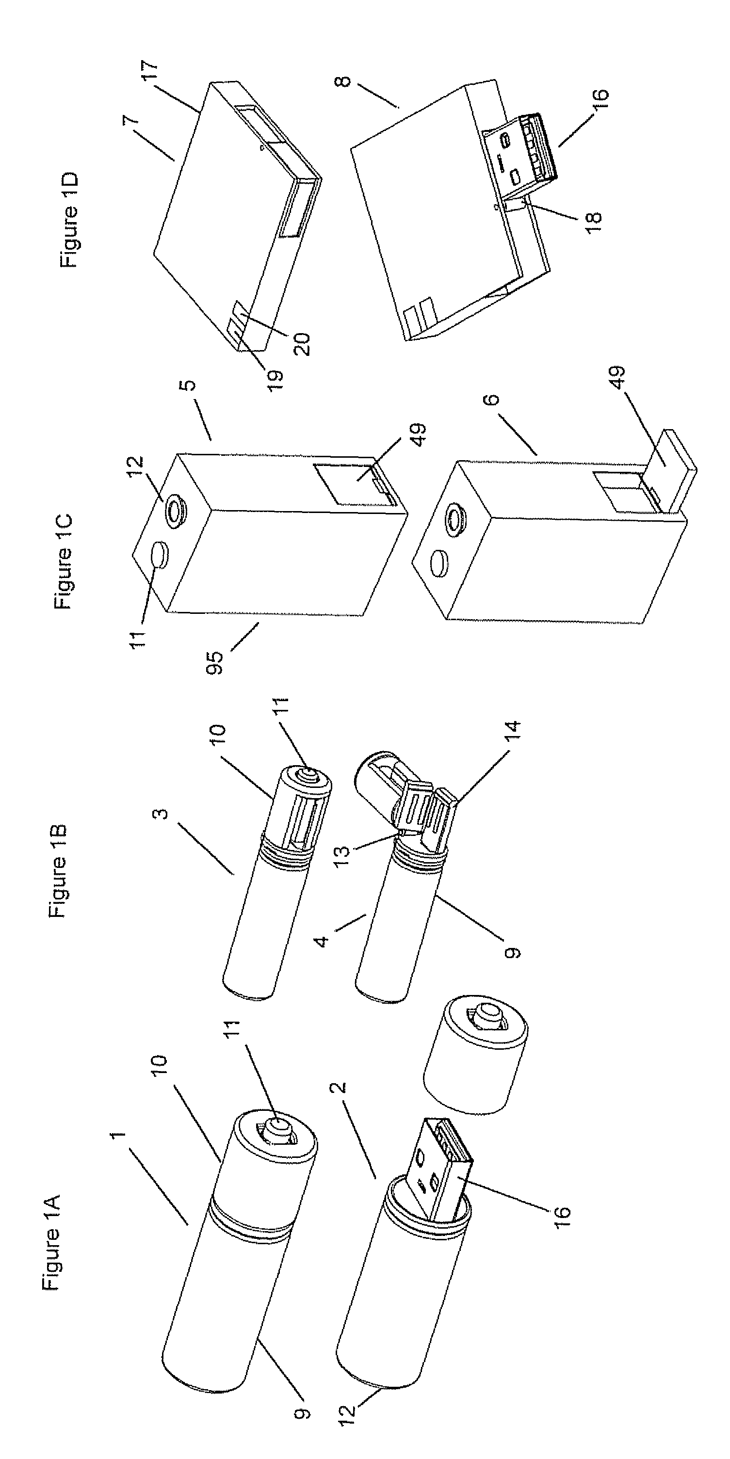
[0030]FIGS. 1A, 1B, 1C, 1D show three dimensional views of example preferred embodiments of rechargeable battery assemblies according to an embodiment of the invention for various conventional battery formats in a deployed and a charge configuration. FIG. 1A shows an AA format cylindrical cell in a deployed configuration 1 and in a charging configuration 2 and comprising a rear section 9, a removable cap 10, an internal connector 16, and having an external positive terminal 11 and negative terminal 12. The rear section 9 may be a battery unit itself or enclose a rechargeable battery unit 15.

[0031]FIG. 1B shows an AAA format cell in a deployed configuration 3 and in a charging configuration 4, with a rear section 9, movable cap 10 that has a hinge 13 and a folding connector 14, and an external positive terminal 11.

[0032]FIG. 1C shows a 9V PP3 prismatic cell in a deployed configuration 5 and in a charging configuration 6 with a casing 95 that encloses rechargeable battery units 15, an...


PUM

PropertyMeasurementUnit
voltageaaaaaaaaaa
voltageaaaaaaaaaa
charge rateaaaaaaaaaa

Abstract

A rechargeable battery assembly comprises a built in connector, circuitry to provide charge control, at least one rechargeable battery unit, and circuitry providing a further function. The battery assembly is mechanically reversible between a deployed configuration having a general form and functions of a conventional battery format and a charge configuration in which the connector is made accessible. In the deployed configuration the battery assembly is capable of providing a discharge to at least one voltage level and can be charged by means of a suitable external charger device. In the charge configuration the battery assembly can be charged by means of the integral charge control circuitry when the connector is connected to a suitable powered receptacle on a computing or peripheral device.

Description

CROSS-REFERENCE TO RELATED APPLICATIONS[0001]This application claims the benefit of priority to U.S. application Ser. No. 60 / 803,149, filed May 25, 2006, the content of which is hereby incorporated by reference herein in its entirety for all purposes.FIELD OF THE INVENTION[0002]The invention relates to a rechargeable battery assembly. The invention relates in preferred embodiments to mechanisms and circuitry for forming a rechargeable battery assembly that has a deployed configuration forming a regular battery format (such as a cylindrical AA, AAA, C, D type cell) or a prismatic cell (such as 9V PP3 format or a camera or “cell” phone battery), and is mechanically reversible to a charging configuration where a integral connector is made accessible to enable charging by means of the internal circuitry when the integral connector is connected to a suitable powered receptacle on a computing or peripheral device.BACKGROUND OF THE INVENTION[0003]A significant problem with rechargeable bat...

Claims


Application Information

Patent Timeline
Patent Type & Authority Patents(United States)
IPC IPC(8): H02J7/00H01M50/296H01M50/553H01M50/559
CPCH01M2/105H01M2/1061H01M2/204H02J7/0031H01M10/4257H01M10/46H01M10/48H01M2/30Y02E60/10H01M50/213H01M50/559H01M50/296H01M50/553
Inventor DANIEL, SIMON RICHARDWRIGHT
Owner MOIXA ENERGY HLDG
Learn More