Drug-eluting tissue marker
a tissue marker and drug-eluting technology, applied in the field of markers, can solve the problems of small biocompatibility of markers, damage to the tissue leading to and at the implantation site, and tissue damage at the site of implantation
- Summary
- Abstract
- Description
- Claims
- Application Information
AI Technical Summary
Benefits of technology
Problems solved by technology
Method used
Image
Examples
first embodiment
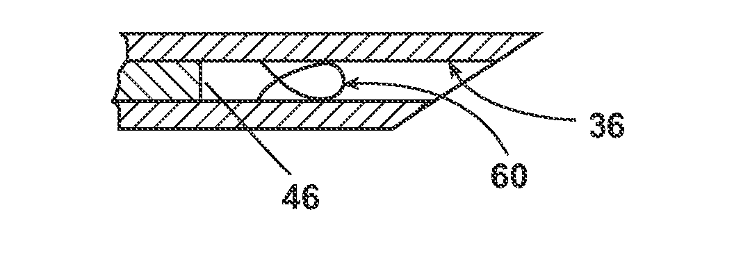
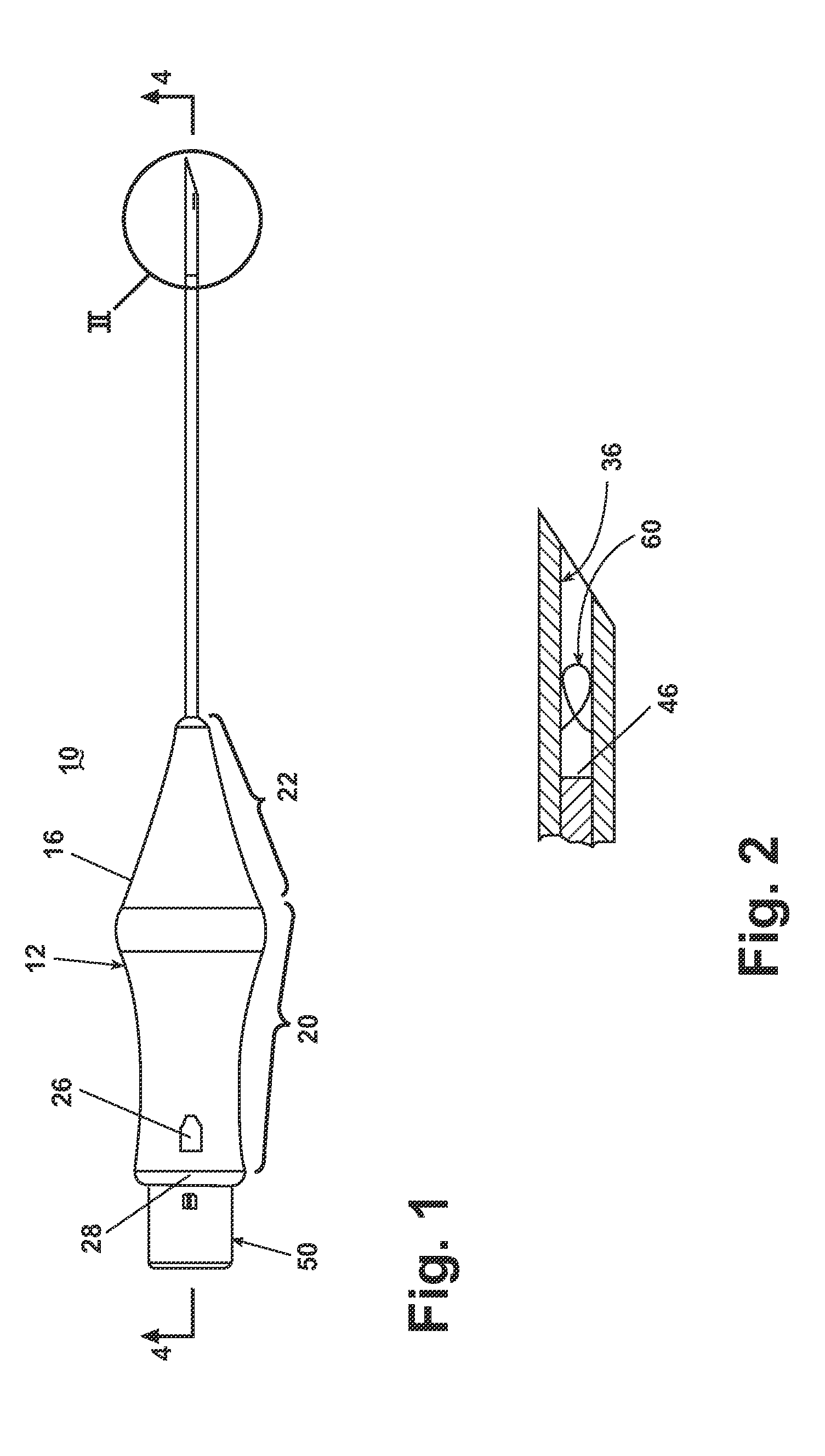
[0049]the marker 60 is shown in FIG. 6 having a bight portion 66 from which extend legs 67, which terminate in tips 68. The tips 68 extend in opposite directions to function as anchors for the marker 60 and help prevent the marker 60 from migrating from the site. The marker 60 further comprises a substrate 62 (partially shown) of underlying material that is coated with a drug 64. As used herein, the term “drug” can include any therapeutic agent, pharmacologic agent, or other substance used for the diagnosis, treatment, or prevention of a disease or as a component of a medication. A coating of the drug 64 can be deposited on the substrate surface using any suitable deposition technique. Alternately, the drug 64 can be embedded in a suitable material, such as a polymer, for timed release of the drug 64. At least a portion of the marker 60 is locatable from the exterior of the patient, through palpitation or through use of an imaging system.
[0050]The substrate 62 can be any number of m...
second embodiment
[0059]the drug-eluting marker is shown in FIG. 7 in which like elements are designated with the same number bearing a prime (′) symbol. The marker 60′ can be comprised of a material 70 containing any of the drugs listed above. In this embodiment, the marker is made of a bioabsorbable material that will dissolve within the body at a predetermined rate, thus releasing the drug in a timed release fashion. Examples of such bioabsorbable materials are collagen, regenerated cellulose, synthetic polymers, and synthetic proteins.
third embodiment
[0060]the drug-eluting marker is shown in FIG. 8 in which like elements are designated with the same number bearing a double-prime (″) symbol. The marker 60″ encapsulates, either fully or partially, the drug 64″. For illustrative purposes, the marker 60″ is shown as a hollow tube 72, made of any of the materials listed above, that encapsulates the drug 64″. Multiple pores 76 extend fully through the tube 72 to allow the drug 64″ to pass through the exterior of the marker 60″. The drug 64″ can also pass through the open ends of the tube 72. The tube 72 can alternately be solid with pores 76, extending only partially through the tube, designed to hold the drug 64″.
[0061]In an alternate design of the third embodiment shown in FIG. 9, where like elements are designated with the same number bearing a triple-prime (′″) symbol, the marker 60′″ can embody a spring-like configuration 82 that fully or partially encapsulates the drug 64′″. The marker 60′″ can further be made of a bioabsorbable...
PUM
| Property | Measurement | Unit |
|---|---|---|
| length | aaaaa | aaaaa |
| size | aaaaa | aaaaa |
| size | aaaaa | aaaaa |
Abstract
Description
Claims
Application Information
 - R&D
- Intellectual Property
- Life Sciences
- Materials
- Tech Scout
- Unparalleled Data Quality
- Higher Quality Content
- 60% Fewer Hallucinations
Browse by: Latest US Patents, China's latest patents, Technical Efficacy Thesaurus, Application Domain, Technology Topic, Popular Technical Reports.
© 2025 PatSnap. All rights reserved.Legal|Privacy policy|Modern Slavery Act Transparency Statement|Sitemap|About US| Contact US: help@patsnap.com


