
Ram booster

a rocket and payload technology, applied in the field of rocket boosters, can solve the problems of large structural mass, limited payload size, and high-speed re-entry tend to require extensive inspection and maintenance, so as to reduce the cost of propelling payloads, reduce the turn-around time and maintenance, and increase the user life

Inactive Publication Date: 2011-11-01
NAT AERONAUTICS & SPACE ADMINISTATION UNITED STATES OF AMERICA AS REPRESENTED BY THE DIRECTOR OF THE
View PDF9 Cites 41 Cited by
  • Summary
  • Abstract
  • Description
  • Claims
  • Application Information

AI Technical Summary

Benefits of technology

[0010]The invention proposed herein comprises a space launch system and method to propel a payload into earth orbit. The upper stage is a production, expendable rocket designed to carry a payload. The lower stage is a booster that is reusable and powered completely by air breathing propulsion. Preferably, the invention includes a middle stage that is also reusable and is also powered completely by air breathing propulsion. A main objective of the system and method is to significantly reduce the costs of propelling payloads, such as satellites, etc., into low-earth orbit by employing a system that provides a reusable booster first stage with significantly increased user life and significantly decreased turn-around time and maintenance compared to current systems.
[0011]Accordingly, it is an objective of this invention to provide a space launch system that reduces turn-around time compared to current systems between launches.
[0012]It is another objective to provide a space launch system of significantly reduced cost to propel a payload into earth orbit compared to current systems.
[0014]It is a further objective of this invention to provide lower and middle stages that do not require a reaction control system.
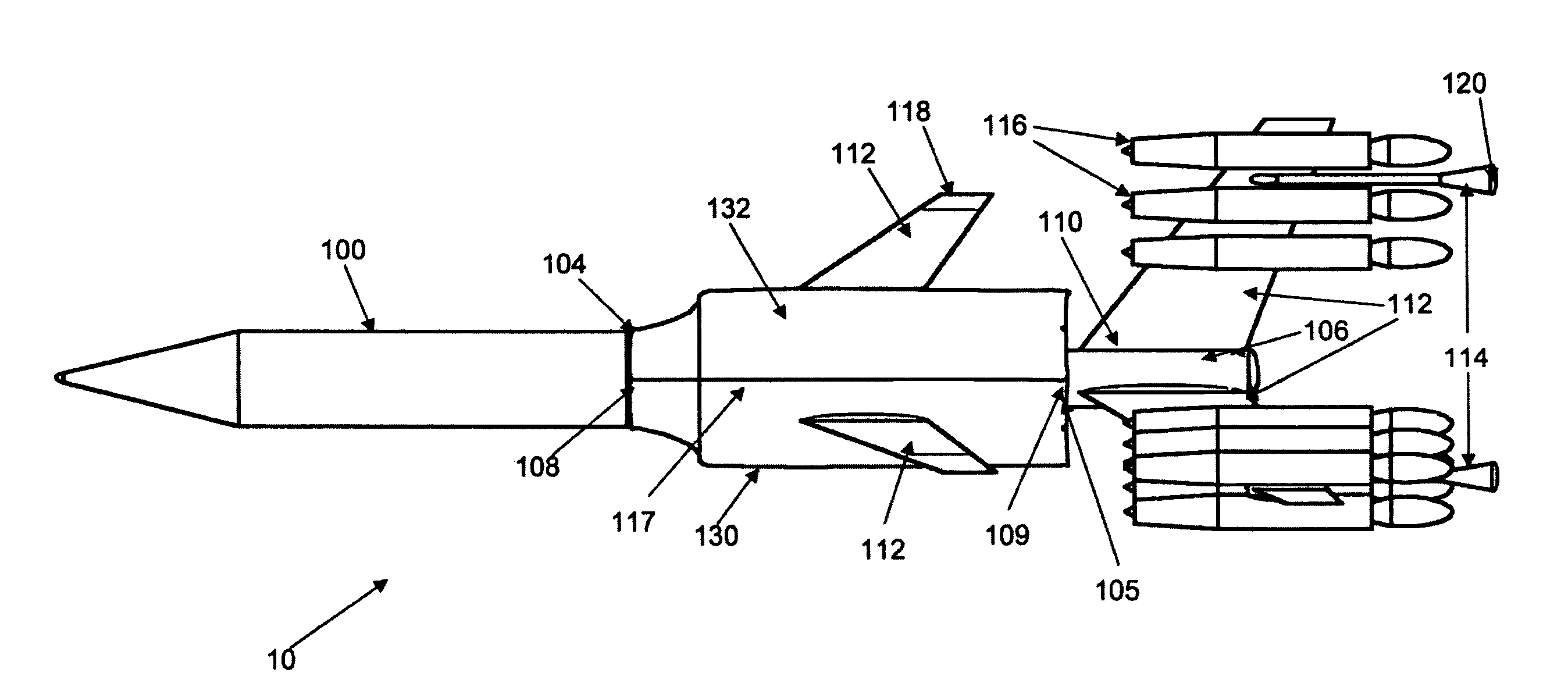
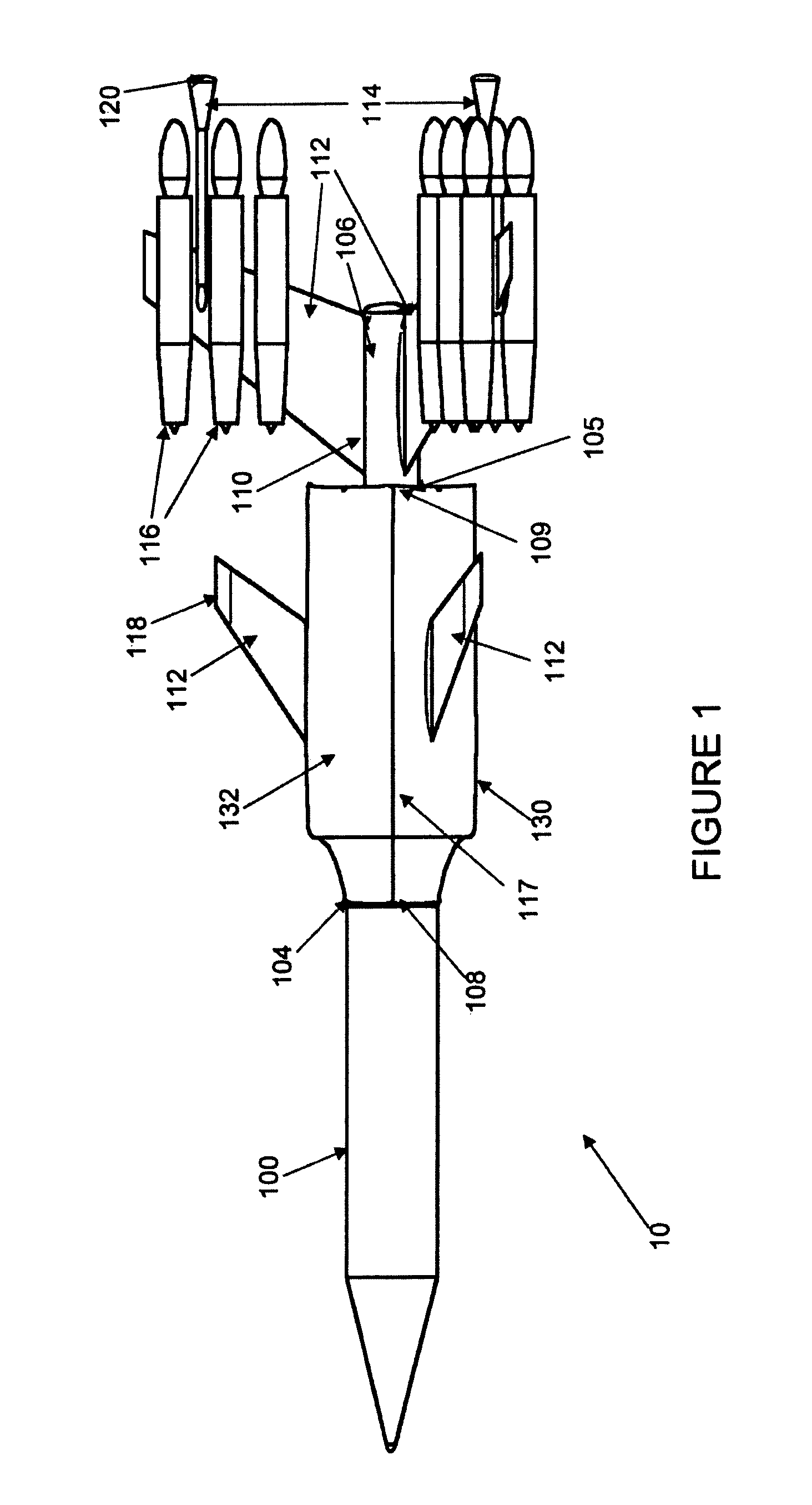
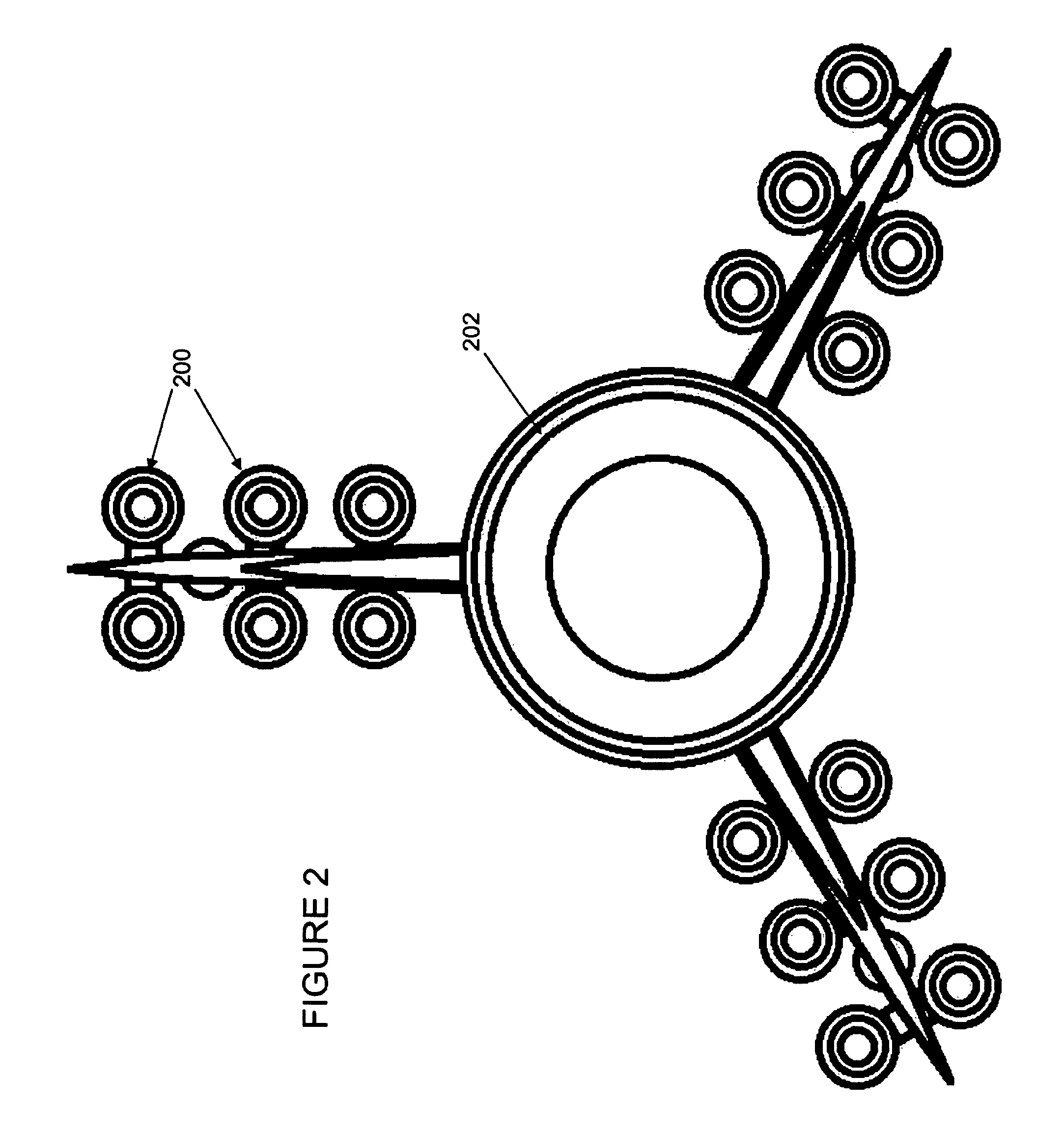
[0015]This invention meets these and other objectives related to propelling payloads into low earth orbit by providing a reusable space launch system booster lower stage and, preferably, middle stage, to help propel a payload bearing rocket upper stage into orbit around the earth. The lower or first stage comprises a cylindrical housing, having a fuel tank containing fuel within the housing, that is releasably attached to the stage above it. A drogue parachute and a plurality of main parachutes are stored in and releasably attached to the housing. A plurality of fins are attached to the outer surface of the housing to provide aerodynamic stability and control. Also, a plurality of landing struts are attached to the fins for landing the reusable booster after each use. A plurality of air breathing engines are attached to the fins and struts, radiating outwards from the housing. A portion of these engines, located outboard of the other engines, employ a system for deflecting the exhausts in tangential directions relative to the circumference of the center tank, allowing directional and roll control at low speeds just after liftoff, and during recovery. The air breathing engines are provided fuel through a connection with the fuel tank in the housing. A preferable middle or second stage comprises a cylindrical housing, having a fuel tank containing fuel within the housing, that is releasably attached to the lower and upper stages. A plurality of fins are also attached to the outer surface of the housing to provide aerodynamic stability and control. The middle stage also has a drogue parachute and a plurality of main parachutes stored therein and either a plurality of air breathing engines attached circumferentially around the housing or an annular air breathing engine surrounding the housing.

Problems solved by technology

Problems with the first approach include the requirement for extremely high fuel mass fractions (>90% of gross liftoff weight “GLOW”), plus the need to put all of the vehicle structural mass into orbit with a very small payload mass fraction (typically <1% of GLOW).
Problems associated with the second approach include expending or requiring refurbishment of a larger structural mass (external tanks expended and solid rocket boosters refurbished in the case of the shuttle).
Also, as evidenced by the space shuttle, the high-speed re-entry tends to require extensive inspection and maintenance during turn-around for subsequent launches.
While achieving reasonable payload mass fractions (relative to the expendable rocket launcher portion), because of physical sizing constraints, this concept currently is limited to about 1000 lbs of payload to orbit, and a fairly high specific launch cost ($ / lbm).
However, this concept still results in numerous deficiencies including requirement for a plurality of different propellants, low useable life for the main rocket stage, requirement for reaction control devices for the main stage, and increased turn-around time for reuse due to the rocket engine main stage.

Method used


Image

  • Ram booster
  • Ram booster
  • Ram booster

Examples


Embodiment Construction

[0025]The present invention is a space launch system and method to propel a payload bearing craft into earth orbit. The invention comprises two or three stages. The upper stage primarily includes rocket engines, propellant tanks, and a payload volume and the upper stage provides the capability of releasably attaching to a lower or middle stage. The lower stage is a reusable booster stage that employs all air breathing engines, is recoverable, and can be turned-around in a short time between missions. Preferably, a middle stage is employed that is a reusable booster stage that also employs all air breathing engines that is also recoverable and can be turned around in a short time between missions. The invention is capable of being practiced using a majority of parts that are currently available “off the shelf” with minor modifications and these parts require significantly less maintenance and preparation between missions than current launch system parts / systems. This results in the a...


PUM


Abstract

The present invention is a space launch system and method to propel a payload bearing craft into earth orbit. The invention has two, or preferably, three stages. The upper stage has rocket engines capable of carrying a payload to orbit and provides the capability of releasably attaching to the lower, or preferably, middle stage. Similar to the lower stage, the middle stage is a reusable booster stage that employs all air breathing engines, is recoverable, and can be turned-around in a short time between missions.

Description

RELATION TO OTHER APPLICATIONS[0001]This application is a continuation-in-part to application Ser. No. 11 / 422,554, filed on Jun. 6, 2006 now abandoned and applicants hereby request this priority date for all subject matter contained herein from said previously filed application.STATEMENT OF GOVERNMENT INTEREST[0002]The invention described herein may be manufactured and used by or for the Government of the United States of America for governmental purposes without payment of any royalties thereon or therefor.BACKGROUND OF THE INVENTION[0003]1. Field of the Invention[0004]The present invention relates generally to propelling a payload into low-earth orbit, more particularly to providing a booster first stage for a payload bearing rocket second stage going to low-earth orbit, and most particularly to providing a reusable, all air-breathing booster first stage for a payload bearing rocket second stage going to low-earth orbit.[0005]2. Description of The Related Art[0006]Most reusable sp...

Claims


Application Information

Patent Timeline
Patent Type & Authority Patents(United States)
IPC IPC(8): B64G1/00
CPCB64D17/04B64D17/72B64G1/002F02K9/00F02K9/76F02K9/78F02K9/94B64G1/006
Inventor BRAND, VANCE D.MORGAN, WALTER RAY
Owner NAT AERONAUTICS & SPACE ADMINISTATION UNITED STATES OF AMERICA AS REPRESENTED BY THE DIRECTOR OF THE
Learn More