Fan operation control method and apparatus

a technology of operation control and fan, applied in the direction of machine/engine, process and machine control, fail safe, etc., can solve the problems of insufficient capacity of electric generator to cover the electric load required to supply electricity to the electrical component at the normally set idle speed, the inability to control the speed of the internal combustion engine, and the inability to operate the fan. to achieve the effect of reducing noise, improving safety, and easy calculation of the fan operating tim

Inactive Publication Date: 2011-10-18
TOYOTA JIDOSHA KK
View PDF18 Cites 3 Cited by
  • Summary
  • Abstract
  • Description
  • Claims
  • Application Information

AI Technical Summary

Benefits of technology

[0012]The invention provides a fan operation control method and apparatus with which it is possible to easily calculate the operating time of the fan and the time required for charging the battery, and it is also possible to suppress noise, improve safety, and extend the lifetime of the battery by reducing unnecessary operations of the fan.
[0014]In this configuration, the operating time of the fan is set in accordance with the outside air temperature based on the fan operating time map, and the idle speed increase time is set in accordance with the set fan operating time based on the idle speed increase time map. This makes it possible to easily calculate the fan operating time and the idle speed increase time for charging the battery, and further, this also makes it possible to reduce operations that are not required and to shorten the idle speed increase time, whereby unnecessary operations are reduced. Thus, it is possible to suppress noise, and improve safety and extend the lifetime of the battery by shortening the operating time.
[0016]Further, when the detected outside air temperature of the vehicle does not match any temperature stored in the fan operating time map, the fan operating time is calculated so as to correspond to the detected outside air temperature, based on other values of the fan operating time stored in the fan operating time map, whereby the fan operating time map covers all the possible outside air temperatures even when the fan operating time map is not set to cover all the possible outside air temperatures. Further, it is possible to reduce the data size of the fan operating time map. As a result, it is possible to reduce the capacity of memory required for storing the data.
[0018]In this configuration, the operating time of the fan is set in accordance with the outside air temperature based on the fan operating time map, and the idle speed increase time is set in accordance with the set fan operating time based on the idle speed increase time map. This makes it possible to easily calculate the fan operating time and the idle speed increase time for charging the battery, and further, this makes it possible to reduce operations of the electric fan that are not required and to shorten the idle speed increase time, whereby unnecessary operations are reduced. Thus, it is possible to suppress noise, and improve safety and extend the lifetime of the battery by shortening the operating time.
[0024]According to the invention, because the operating time of the fan is set in accordance with the outside air temperature based on the fan operating time map, and the idle speed increase time is set in accordance with the set fan operating time based on the idle speed increase time map, it is possible to provide fan operation control method and apparatus with which it is possible to easily calculate the fan operating time and the idle speed increase time for charging the battery, and further, it is possible to suppress noise, and improve safety and extend the lifetime of the battery by reducing unnecessary operations.

Problems solved by technology

This makes an air-fuel ratio in each cylinder significantly leaner than a desired air fuel ratio, which can result in unstable engine speed during idling operation (hereinafter referred to as “idle speed”) and can significantly reduce startability of the internal combustion engine.
On the other hand, even during normal operation of the internal combustion engine, if an electrical component that consumes a large amount of electricity is used during idling, the capacity of the electric generator becomes insufficient to cover the electric load required to supply electricity to the electrical component at the normally set idle speed.
It is difficult to accurately measure these values, and as a result, it is also difficult to calculate the fan operating time.
Further, according to the technology described in JP-A-2006-525462, because the operating time of the fan after the internal combustion engine is stopped fluctuates, it is not possible to effectively charge the battery to compensate for the decrease in the battery charge amount.
For example, if a battery charging time is set in order to sufficiently charge the battery at all times, the battery is unnecessarily charged when the operating time of the fan is short.
Therefore, a plurality of devices, such as a comparator and a delay circuit, are required, and further, a complicated circuit is also required.
Further, according to the technology described in JP-A61-70149, the idle speed can be increased only when the battery is discharging, and it is not possible to deal with the decrease in the battery charge amount after the internal combustion engine is stopped.

Method used


Image

  • Fan operation control method and apparatus
  • Fan operation control method and apparatus
  • Fan operation control method and apparatus

Examples


Embodiment Construction

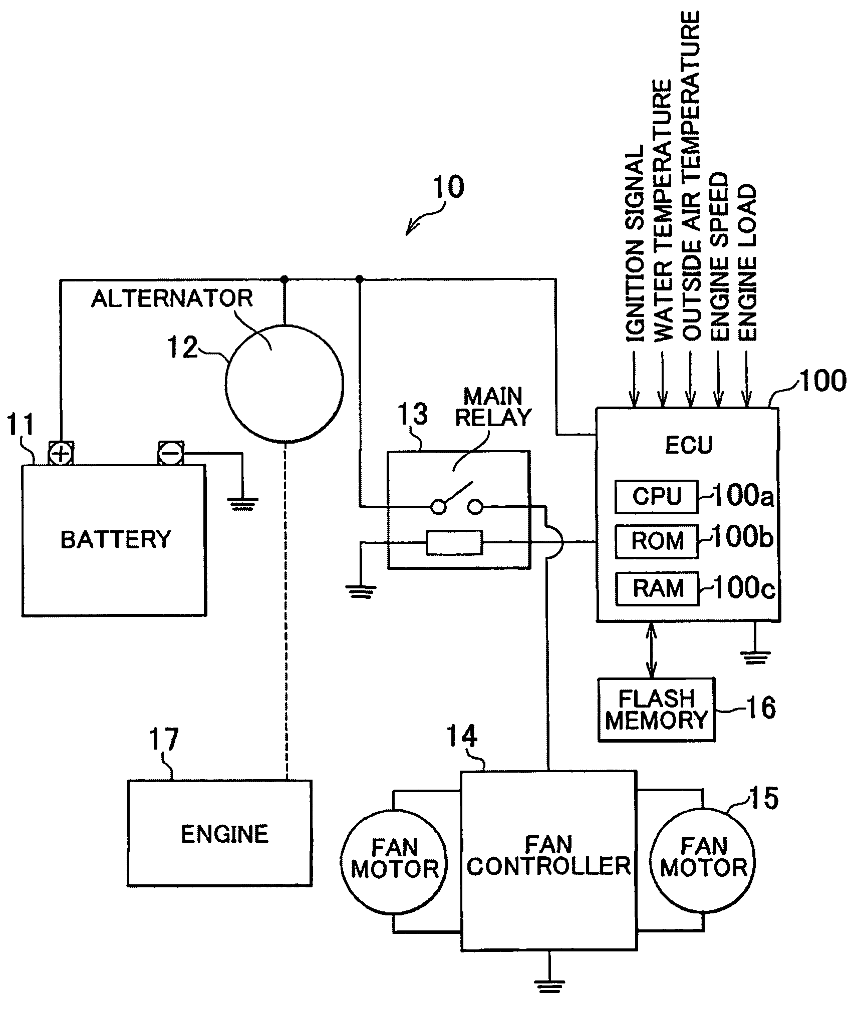
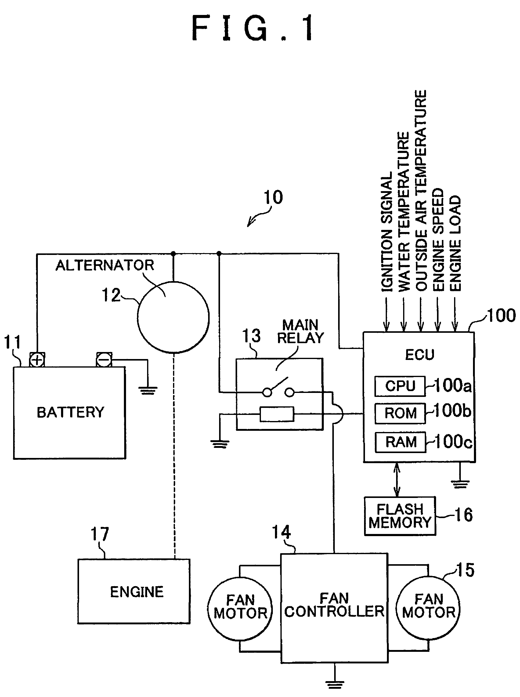
[0034]An embodiment of the invention will be described with reference to the attached drawings. It should be noted that directional terms used in this specification, front and rear, for example, describe the directions with respect to a vehicle. First, the configuration of a vehicle to which a fan operation control apparatus according to the embodiment of the invention is mounted will be described. FIG. 1 is a block diagram schematically showing the vehicle to which the fan operation control apparatus according to the embodiment of the invention is mounted.

[0035]As shown in FIG. 1, acvehicle 10 includes: a battery 11 that functions as an electric accumulator; an alternator 12 that functions as an electric generator; a main relay 13 that opens and closes a circuit; a fan motor 15; a fan controller 14 that controls the fan motor 15; a flash memory 16 that is a non-volatile memory; an engine 17, which is an internal combustion engine; and a vehicle electronic control unit (hereinafter ...


PUM


Abstract

An outside air temperature of a vehicle is detected, an operating time of a fan is set in accordance with the detected outside air temperature based on a fan operating time map, and an idle speed increase time is set in accordance with the an operating time based on an idle speed increase time map.

Description

INCORPORATION BY REFERENCE[0001]The disclosure of Japanese Patent Application. No. 2007-329060 filed on Dec. 20, 2007 including the specification, drawings and abstract is incorporated herein by reference in its entirety.BACKGROUND OF THE INVENTION[0002]1. Field of the Invention[0003]The invention relates to a fan operation control method and apparatus to control an operating time of an electric fan that cools an internal combustion engine after the internal combustion engine is stopped and an idle speed increase time required for charging the battery.[0004]2. Description of the Related Art[0005]Typically, an internal combustion engine mounted on a vehicle, for example, is relatively hot immediately after the internal combustion engine is stopped. If the internal combustion engine is restarted under such circumstances, fuel in a fuel pipe of a fuel injection system becomes hot (for example, approximately 100° C.), and therefore, bubbles (fuel vapor) are formed and thus the amount of...

Claims


Application Information

Patent Timeline
Patent Type & Authority Patents(United States)
IPC IPC(8): G05D1/00F01P7/10H02J7/00B60Q1/00F01P7/04
CPCF01P7/08F01P2005/046F01P2025/13F01P2031/30
Inventor KYUMA, TAKAHIDE
Owner TOYOTA JIDOSHA KK
Why Eureka
Try Eureka