Fluorescence detection apparatus and method, and prism used therein
a fluorescence detection and apparatus technology, applied in the direction of optical radiation measurement, instruments, spectrophotometry/monochromators, etc., can solve the problem of bleaching in some fluorescent spots before they are observed, the signal-noise ratio (s/n) of detection is reduced, and the cost of increasing excitation power is increased. problem, to achieve the effect of low cost, high processing capacity and high sensitivity
- Summary
- Abstract
- Description
- Claims
- Application Information
AI Technical Summary
Benefits of technology
Problems solved by technology
Method used
Image
Examples
first embodiment
[0058]FIG. 6 is a side view of showing the schematic configuration of the fluorescence detection apparatus 100 according to the first embodiment of this invention. The fluorescence detection apparatus includes a laser light source (hereinafter referred to as “light source”) 6, a beam cross section shaping unit 8 for shaping the incident beam to the predetermined shape, a mirror 9 for reflecting the beam in the predetermined direction, a transparent body 1 for performing the function of a triangular prism and that of the substrate for mounting the sample 2, a cover glass 10 for covering the sample 2, an objective lens 12 for collecting and collimating the irradiated fluorescence, a filter 13 for removing the scattered light element contained in the fluorescence, an imaging lens 14 and a detector 15 (for example, CCD and CMOS sensors).
[0059]In the fluorescence detection apparatus 100 having such a configuration, the output beam 7 from the light source 6, after passing through the beam...
second embodiment
[0067]FIG. 14 is a side view showing the schematic configuration of the fluorescence detection apparatus 101 according to the second embodiment of this invention. The fluorescence detection apparatus 101 has basically the same configuration as the fluorescence detection apparatus 100 according to the first embodiment. However, an aspherical lens without rotational symmetry around the optical axis is used in the place of an anamorphic prism as the beam cross section shaping unit 8.
[0068]In this embodiment, a cylindrical lens 8-c with a focal distance of 75 mm and a cylindrical lens 8-d with a focal distance of 25 mm are used as the beam cross section shaping unit 8. And this converts a circular laser output beam 1.2 mm in diameter to a beam ds=1.2 mm and dp=0.4 mm. In this embodiment, the beam cross section length is converted only in the p direction (see FIG. 5). However, it is possible to convert both beam cross section lengths by using an aspherical lens having curvature in two di...
third embodiment
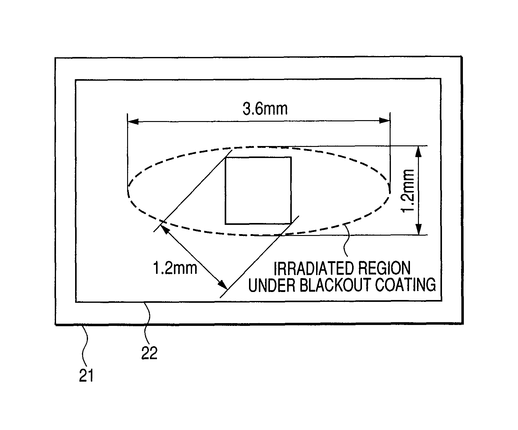
[0070]FIG. 15 is a side view showing the schematic configuration of the fluorescence detection apparatus 102 according to the third embodiment of this invention. The fluorescence detection apparatus 102 has basically the same configuration as the fluorescence detection apparatus 100 according to the first embodiment. However, it has no beam cross section shaping unit 8 and uses a semiconductor laser outputting a beam whose section has an aspect ratio of 0.33 as a light source 61. It is possible to bring the aspect ratio of the irradiated region to 1 without any beam cross section shaping unit by using a laser that outputs a beam having a cross section whose aspect ratio is cos θ against the incident angle θ for total internal reflection.
[0071]According to this embodiment, the configuration of the fluorescence detection apparatus is simplified, and has the effect of reducing the cost.
PUM
| Property | Measurement | Unit |
|---|---|---|
| aspect ratio | aaaaa | aaaaa |
| aspect ratio | aaaaa | aaaaa |
| aspect ratio | aaaaa | aaaaa |
Abstract
Description
Claims
Application Information
 - R&D
- Intellectual Property
- Life Sciences
- Materials
- Tech Scout
- Unparalleled Data Quality
- Higher Quality Content
- 60% Fewer Hallucinations
Browse by: Latest US Patents, China's latest patents, Technical Efficacy Thesaurus, Application Domain, Technology Topic, Popular Technical Reports.
© 2025 PatSnap. All rights reserved.Legal|Privacy policy|Modern Slavery Act Transparency Statement|Sitemap|About US| Contact US: help@patsnap.com


