
Stent prosthesis having select flared crowns

a stent and crown technology, applied in the field of stent prosthesis, can solve the problems of inability to fix the vessel, the stent prosthesis is not used in percutaneous heart valve applications, and the coronary artery disease is a major cause of death, and the stent prosthesis does not have the vessel fixation properties

Inactive Publication Date: 2011-10-11
MEDTRONIC VASCULAR INC
View PDF12 Cites 38 Cited by
  • Summary
  • Abstract
  • Description
  • Claims
  • Application Information

AI Technical Summary

Benefits of technology

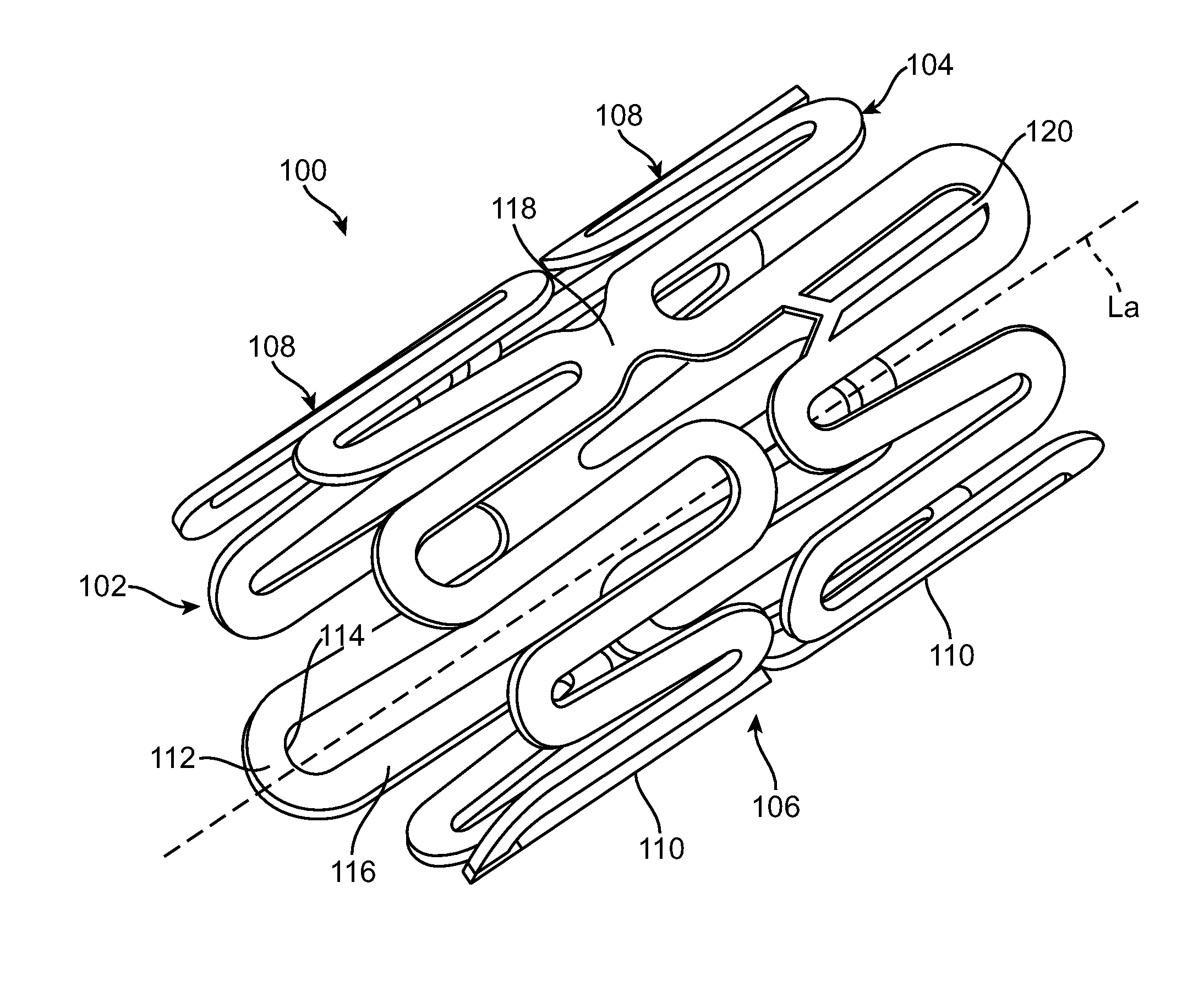
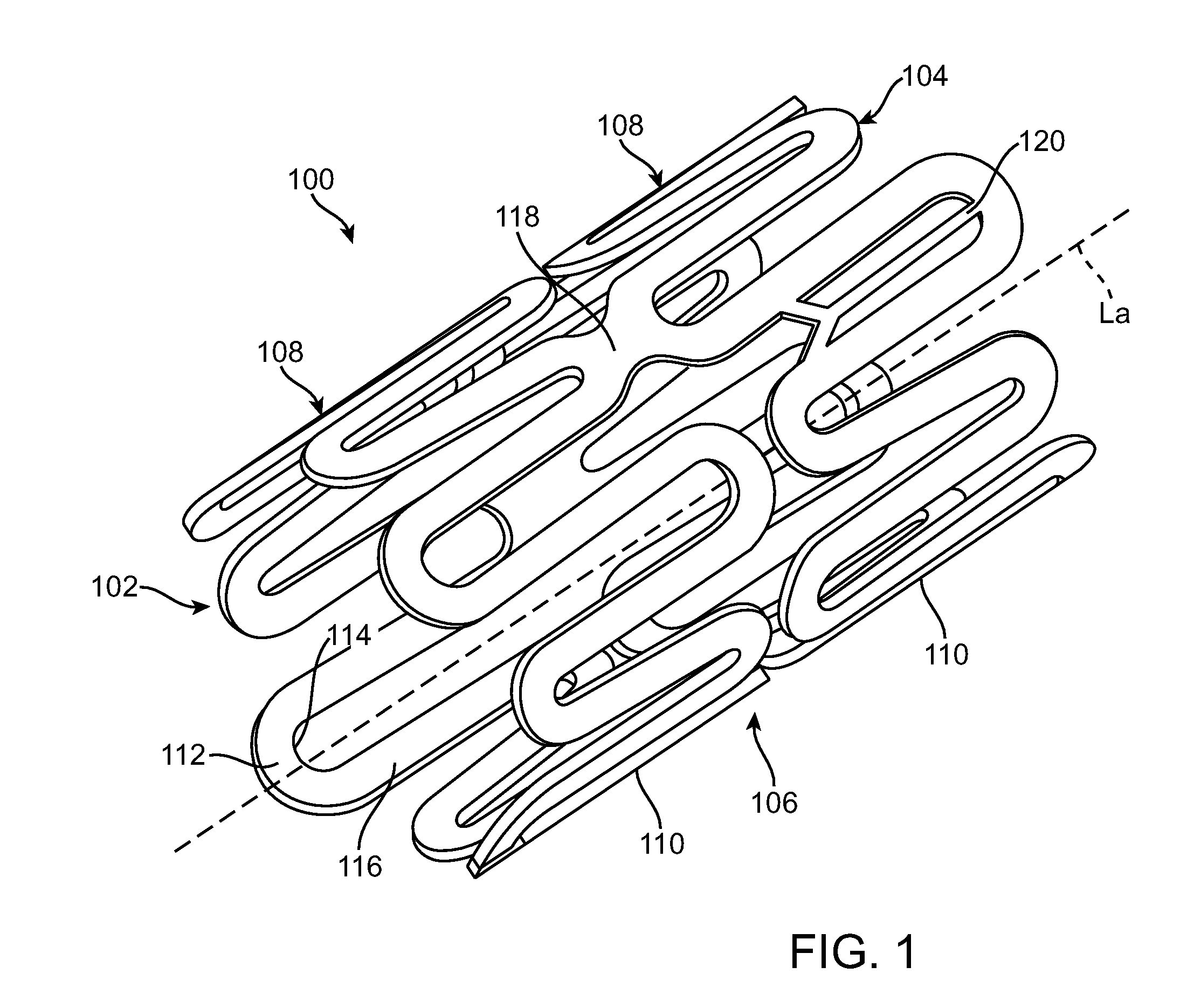
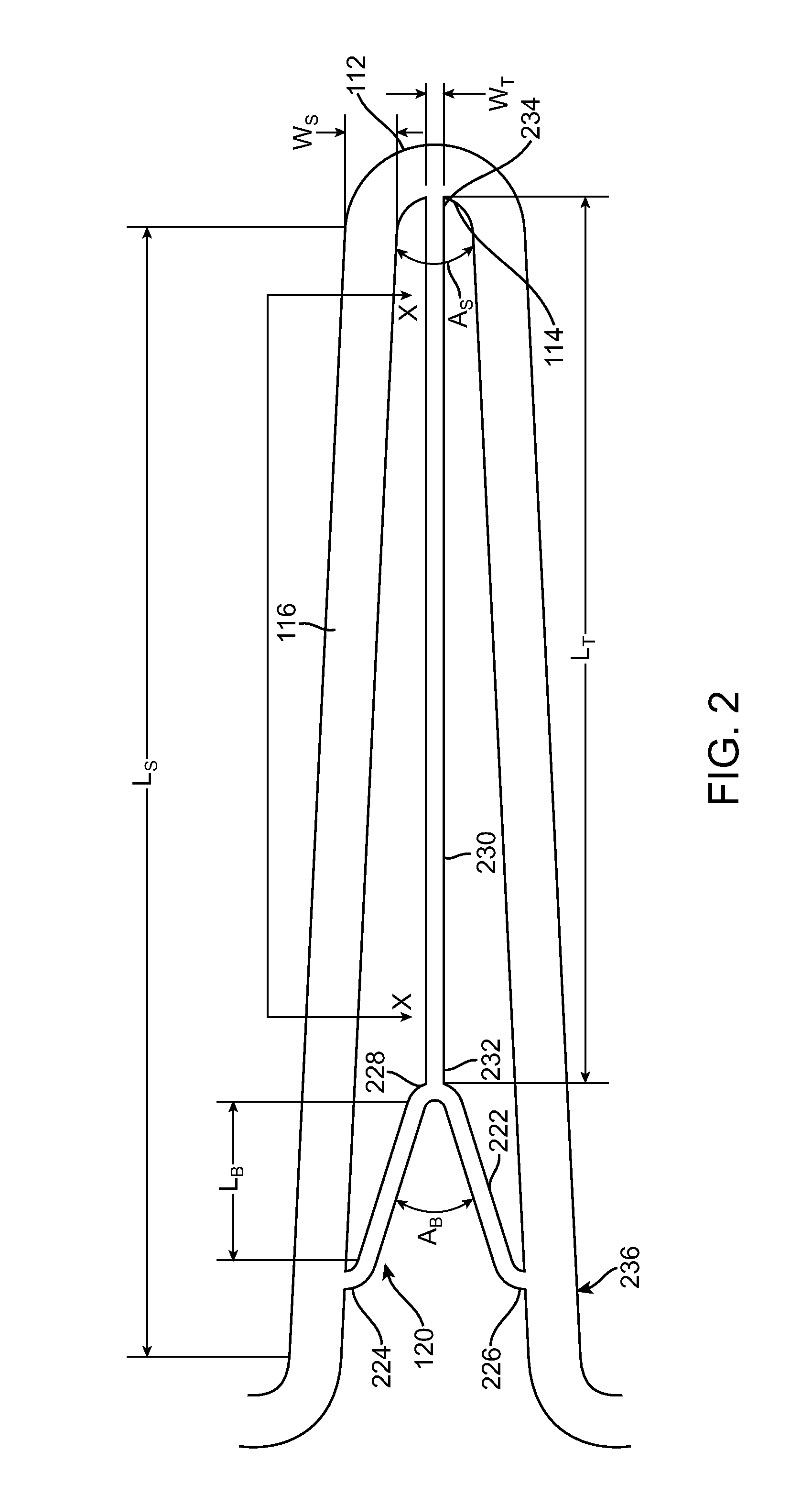
The present invention relates to a stent for use in a body lumen. The stent has a unique design with straight segments and crowns that create a sinusoidal pattern. The stent also includes a Y-shaped member attached to one of the crowns. When the stent is expanded to contact the vessel wall, the Y-shaped member causes the crown to flare outward from the stent, creating an acute angle with respect to the stent's longitudinal axis. This design helps to improve the stent's ability to support the body lumen and maintain its patent text describes a stent with a unique design that helps to support the body's blood vessels. The stent has straight segments and crowns that create a sinusoidal pattern. It also includes a Y-shaped member attached to one of the crowns. When the stent is expanded to contact the vessel wall, the Y-shaped member causes the crown to flare outward from the stent, creating an acute angle with respect to the stent's longitudinal axis. This design helps to improve the stent's ability to support the body lumen.

Problems solved by technology

Heart disease, specifically coronary artery disease, is a major cause of death, disability, and healthcare expense in the United States and other industrialized countries.
Stents prostheses, including those used in percutaneous heart valve applications, often do not have vessel fixation properties other than providing a coaxial interference fit into the target vessel or location.

Method used


Image

  • Stent prosthesis having select flared crowns
  • Stent prosthesis having select flared crowns
  • Stent prosthesis having select flared crowns

Examples


Embodiment Construction

[0022]Specific embodiments of the present invention are now described with reference to the figures, wherein like reference numbers indicate identical or functionally similar elements. The terms “distal” and “proximal” are used in the following description with respect to a position or direction relative to the treating clinician. “Distal” or “distally” are a position distant from or in a direction away from the clinician. “Proximal” and “proximally” are a position near or in a direction toward the clinician.

[0023]The following detailed description is merely exemplary in nature and is not intended to limit the invention or the application and uses of the invention. Although the description of the invention is in the context of treatment of blood vessels such as the coronary, carotid and renal arteries, the invention may also be used in any other body passageways where it is deemed useful. Furthermore, there is no intention to be bound by any expressed or implied theory presented in ...


PUM


Abstract

A generally tubular, cylindrical stent prosthesis has an unexpanded delivery configuration and an expanded configuration for contacting the vessel wall. The stent prosthesis has a plurality of adjacent stent struts, each stent strut having a wavelike or sinusoidal pattern of straight segments and crowns. A Y-shaped member is attached to one or more crowns to cause the crowns to flare outwardly at an angle from the cylindrical stent body when the stent is expanded. Upon expansion of the stent, the crown(s) having Y-shaped members attached thereto are angled with respect to the longitudinal axis and radially flare from the cylindrical stent body. The flared crowns anchor the stent within the vessel by protruding into the vessel wall and / or seating the stent within an ostium.

Description

FIELD OF THE INVENTION[0001]The present invention is directed to a stent prosthesis for use in a body lumen. More particularly, the present invention is directed to a stent prosthesis design to induce flaring of select stent crowns.BACKGROUND OF THE INVENTION[0002]Heart disease, specifically coronary artery disease, is a major cause of death, disability, and healthcare expense in the United States and other industrialized countries. A number of methods and devices for treating coronary heart disease have been developed, some of which are specifically designed to treat the complications resulting from atherosclerosis and other forms of coronary arterial narrowing.[0003]One method for treating such conditions is percutaneous transluminal coronary angioplasty (PTCA). Generally, PTCA is a procedure that involves passing a balloon catheter over a guidewire to a stenosis with the aid of a guide catheter. The stenosis may be the result of a lesion such as a plaque or thrombus. The guidewir...

Claims


Application Information

Patent Timeline
Patent Type & Authority Patents(United States)
IPC IPC(8): A61F2/06A61F2/82
CPCA61F2/91A61F2/915A61F2230/0054A61F2002/821A61F2230/005A61F2/958
Inventor PELLEGRINI, GIANFRANCO
Owner MEDTRONIC VASCULAR INC
Learn More