
Manually adjustable ruggedized focus mechanism

a focus mechanism and adjustable technology, applied in the field of image acquisition, can solve the problems of prone to failure, high cost, and high risk of exposing the lens to potentially harmful factors, and achieve the effects of avoiding re-positioning, avoiding repositioning, and avoiding repositioning

Inactive Publication Date: 2011-10-11
COGNEX CORP
View PDF47 Cites 6 Cited by
  • Summary
  • Abstract
  • Description
  • Claims
  • Application Information

AI Technical Summary

Benefits of technology

[0013]Such devices include, in one aspect of the invention, an image capture medium (e.g., a CMOS sensor, CCD array, etc.) that is disposed within an enclosure and an optics assembly that is also disposed within that enclosure, rotatably. The optics assembly, which includes at least a lens, can have a cylindrical outer diameter along at least a portion of its length that is received within the enclosure along a length that has a corresponding cylindrical inner diameter. A first seal (e.g., an “O-ring”) is disposed between, and in contact with, the optics assembly and the enclosure, e.g., along these corresponding lengths. That seal permits rotation (or direct translation, e.g., by pushing or pulling) of the optics assembly for purposes of focusing the lens, while preventing (or reducing a risk of) contamination from the environment (e.g., water, chemicals, dirt, dust, etc.) from entering into the enclosure and vice versa.
[0015]In another aspect, the invention provides a device for image acquisition as described above in which the optics assembly includes a lens sub-assembly and a window sub-assembly. The lens sub-assembly includes the lens, while the window sub-assembly includes an optically transparent cover (e.g., a window) and, for example, a focusing ring. The cover / window protects the lens and other image acquisition components that are within the enclosure from the environment, while permitting passage of light (or other rays) comprising images to be captured. The focusing ring facilitates grasping the window sub-assembly (and, more generally, the optics assembly) for purposes of rotating the assembly relative to the enclosure and / or rotating the window sub-assembly relative to the lens sub-assembly—and thereby facilitates focusing the lens, e.g., on the CMOS, CCD or other capture medium.
[0017]As a result of a friction fit, that seal also permits at least partial coupling of the lens and window sub-assemblies, e.g., so that rotation of the focus ring (particularly) and / or the window sub-assembly (generally) translates to the lens sub-assembly and, thereby, facilitates focusing the lens. Because that rotational friction can be overcome, at least in some aspects of the invention, the seal can prevent excess rotation of the focus ring (particularly) and / or the window sub-assembly (generally) from being translated to the lens and, thereby, for example, from stripping lens-mount threading.
[0019]In related aspects of the invention, that coupling is provided via corresponding threading on the lens sub-assembly (or lens itself) and a mount in the enclosure. That threading can include sealing materials, such as silicone, rubber, etc. to prevent any contamination that might have entered the enclosure from reaching the lens and / or the CCD or (image capture medium).

Problems solved by technology

Not only is this inconvenient, but it runs the risk of exposing the lens to potentially harmful factors.
Moreover, such adjustment often requires the use of particular tools, which can be expensive and complicated to use.
The drawbacks of the former are that the motorized mechanisms are more complicated, expensive, and prone to failure, e.g., due to power loss, breakage, and so on.
The drawbacks of the latter are that if an operator fails to set or release a lock, focussing may be substantially impaired.

Method used


Image

  • Manually adjustable ruggedized focus mechanism
  • Manually adjustable ruggedized focus mechanism
  • Manually adjustable ruggedized focus mechanism

Examples


Embodiment Construction

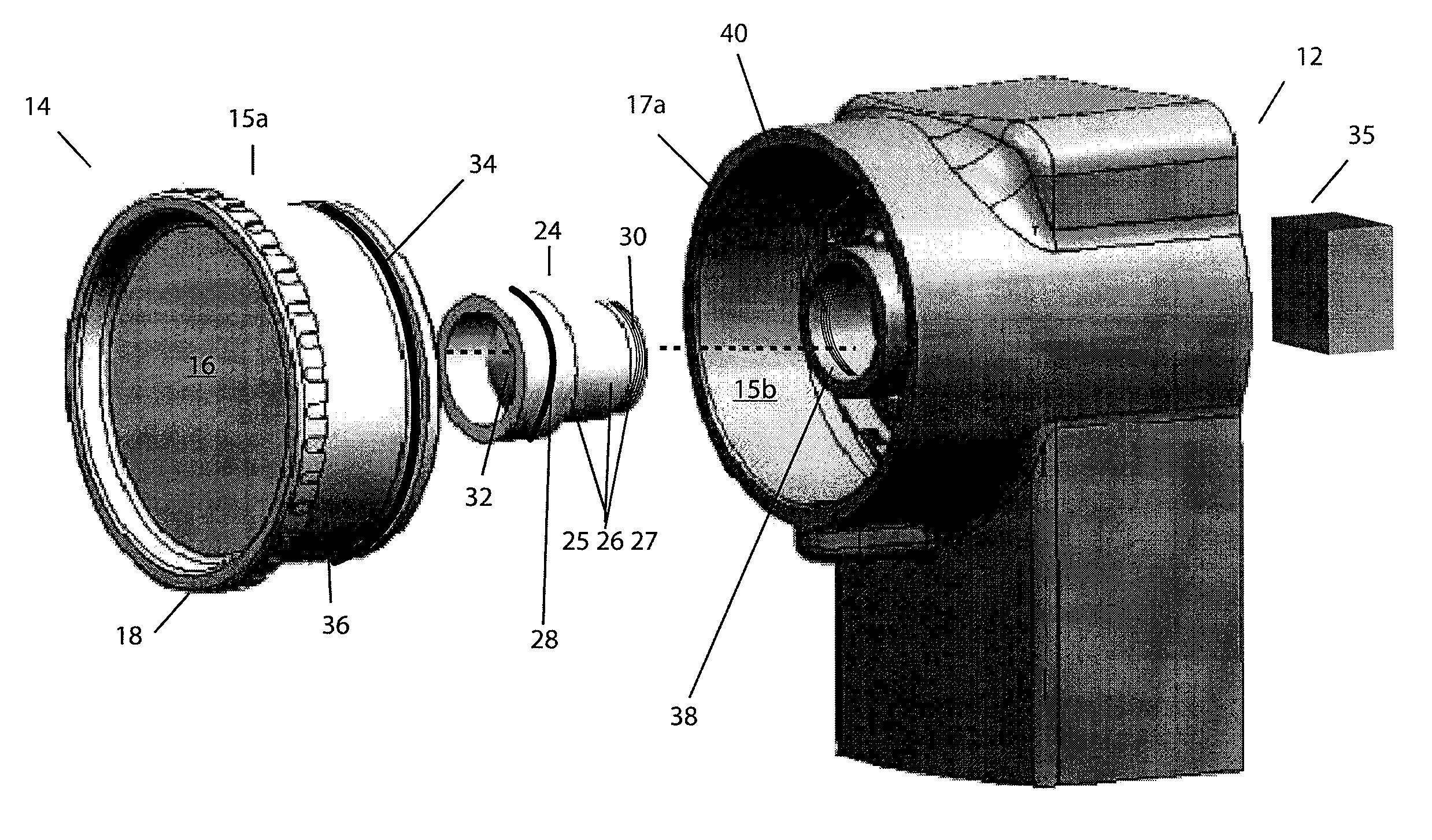
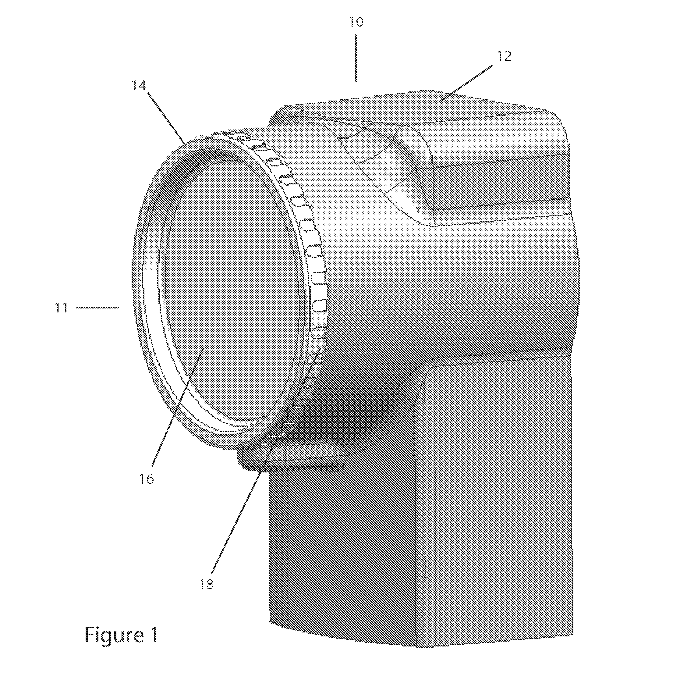
[0027]FIG. 1 depicts an image acquisition device 10 according to one practice of the invention. The device 10 includes a enclosure 12 having an optics assembly 11 rotatably disposed therein. The enclosure 12 houses components of the image acquisition device (e.g., a lens 32, an image capture medium, etc., as discussed below), protecting them from dust, dirt, water, moisture, and / or other elements of the surrounding environment (or more broadly, preventing an exchange or transfer of unwanted elements between the enclosure 12 and the environment). In the illustrated embodiment, enclosure 12, which may be “ruggedized,” comprises ceramic, metal, plastic and / or other materials suitable for providing such protection under the device's 10 expected operating conditions.

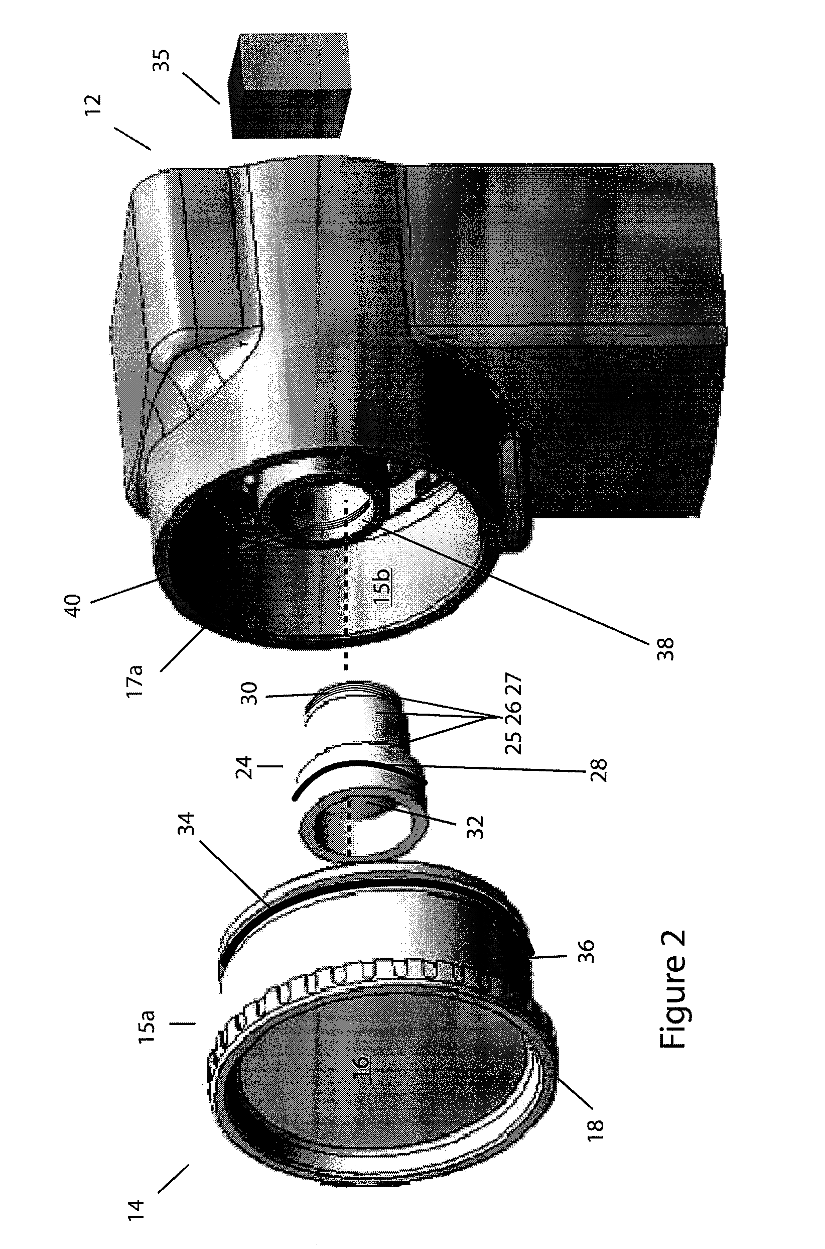
[0028]FIG. 2 is an exploded view of the enclosure 12 and the optics assembly 11. The illustrated optics assembly 11 comprises a lens sub-assembly 24 that is coupled to a window sub-assembly 14 as discussed below. The window s...


PUM


Abstract

The invention provides, in some aspects, devices for image acquisition that use seals (e.g., O-rings) between concentrically disposed portions of an enclosure and an optics assembly (or sub-assemblies thereof) in order to protect image acquisition components from the surrounding environment (and vice versa) while, at the same time, providing adequate friction for both adjusting and locking focus. Such devices include, in one aspect of the invention, an image capture medium (e.g., a CMOS sensor, CCD array, etc.) that is disposed within an enclosure and an optics assembly that is also disposed within that enclosure, rotatably. The optics assembly, which includes at least a lens, can have a cylindrical outer diameter along at least a portion of its length that is received within the enclosure along a length that has a corresponding cylindrical inner diameter. A first seal (e.g., an “O-ring”) is disposed between, and in contact with, the optics assembly and the enclosure, e.g., along these corresponding lengths. That seal permits rotation of the optics assembly for purposes of focusing the lens, while preventing (or reducing a risk of) contamination from the environment (e.g., water, chemicals, dirt, dust, etc.) from entering into the enclosure and vice versa.

Description

BACKGROUND OF THE INVENTION[0001]The invention pertains to image acquisition and, more particularly, to image acquisition devices that can be manually adjusted and that are sealed to the elements, e.g., water, chemicals, dirt, dust.[0002]Image acquisition refers to the capture of still or video images. It forms a basis for “machine vision,” i.e., the computer processing of images, and is used in manufacturing and industry for robotic assembly, parts inspection, quality control, etc. It is also increasingly used in military and security, as well as commercial and residential, applications.[0003]Image acquisition devices, or “cameras” as they are commonly called, optimally utilize adjustable focus lenses. These have an advantage over fixed-focus lenses in that they permit optics (e.g., lens “glass”) to be set at optimal focal points for objects at varying distances, thus insuring sharpness of both close (or far) objects.[0004]In traditional industrial and manufacturing image acquisiti...

Claims


Application Information

Patent Timeline
Patent Type & Authority Patents(United States)
IPC IPC(8): G02B23/16G02B13/16G02B7/02G02B7/04
CPCG03B17/08G02B7/04Y10S359/90G03B2217/002
Inventor COSTIGAN, GEORGEGOODSPEED, STEVEN N.TREMBLAY, ROBERT J.KEATING, JOHN F.PHILLIPS, BRIAN S.HOFFMASTER, JAMES
Owner COGNEX CORP
Learn More