Pneumatic tire with tread having thin groove and sacrifice land portion having protruding portion

a technology of pneumatic tires and grooves, which is applied in the direction of non-skid devices, vehicle components, transportation and packaging, etc., can solve the problems of reducing the preventive effect of tire irregular wear, crack generation cannot be satisfactorily prevented, and the durability of conventional tires is affected, so as to prevent crack generation in the groove bottom, prevent the effect of irregular wear and ensure the rigidity of the main land portion

Active Publication Date: 2011-10-11
TOYO TIRE & RUBBER CO LTD
View PDF12 Cites 0 Cited by
  • Summary
  • Abstract
  • Description
  • Claims
  • Application Information

AI Technical Summary

Benefits of technology

[0008]The present invention has been made in view of the above described circumstances. An object of the present invention is to provide a pneumatic tire capable of effectively preventing the generation of cracks at the groove bottom of thin groove while ensuring its irregular wear proof performance.
[0010]According to the present invention, the thin groove includes the enlarged portion extending in the circumferential direction of the tire, in which the groove width at the groove bottom is enlarged toward the sacrifice land portion side only. With this arrangement, the generation of cracks in the groove bottom can be prevented and the rigidity of the main land portion can be satisfactorily ensured. Even when the sacrifice land portion receives a force from a road surface and is tilted onto the main land portion, the main land portion is prevented from being deformed, and thus the irregular wear thereof can be prevented. Further, the thin groove includes the protruding portion that protrudes toward the groove bottom side along the inner wall located at the sacrifice land portion side and extends in the circumferential direction of the tire. Therefore, even when the thin groove is deformed in a direction that the thin groove is squashed particularly upon receiving a lateral force, the protruding portion comes into contact with the inner wall located at the main land portion side first and supports the enlarged portion, so that the enlarged portion is prevented from being squashed completely. With this arrangement, the curvature radius at the groove bottom is ensured a certain extent, and thus the generation of cracks in the groove bottom can be effectively prevented. As a result, the pneumatic tire of the present invention can ensure both of the irregular wear proof performance and the crack proof performance at the groove bottom of the thin groove.
[0011]In the pneumatic tire mentioned hereinbefore, it is preferable that the protruding portion has a front end portion having a circular shape in section, and when defining a maximum groove width of the enlarged portion as W and a maximum width of the protruding portion as W1, the relationship therebetween is 0.25≦W1 / W≦0.65. According to the above arrangement, since the width of the protruding portion is optimally ensured, the enlarged portion can be effectively prevented from being squashed and the curvature radius at the groove bottom can be ensured. Accordingly, the generation of cracks in the groove bottom can be prevented further effectively.

Problems solved by technology

However, when the tire receives a force from a road surface during running and when a sacrifice land portion thereof is deformed excessively, this causes stress convergence at the bottom of the groove and thereby results in cracks.
Thus, conventional tires have had a problem in the aspect of the durability thereof.
However, in this case, there arises such a problem that the sacrifice land portion 11 itself is broken away or the preventive effect against the irregular wear of the tire is reduced.
As a result, the crack generation cannot be satisfactorily prevented.
As a result, the rigidity of the sacrifice land portion 14 cannot be ensured.
Therefore, there is a limitation for increasing the curvature radius at the groove bottom of the thin groove 15.

Method used


Image

  • Pneumatic tire with tread having thin groove and sacrifice land portion having protruding portion
  • Pneumatic tire with tread having thin groove and sacrifice land portion having protruding portion
  • Pneumatic tire with tread having thin groove and sacrifice land portion having protruding portion

Examples


examples 1 and 2

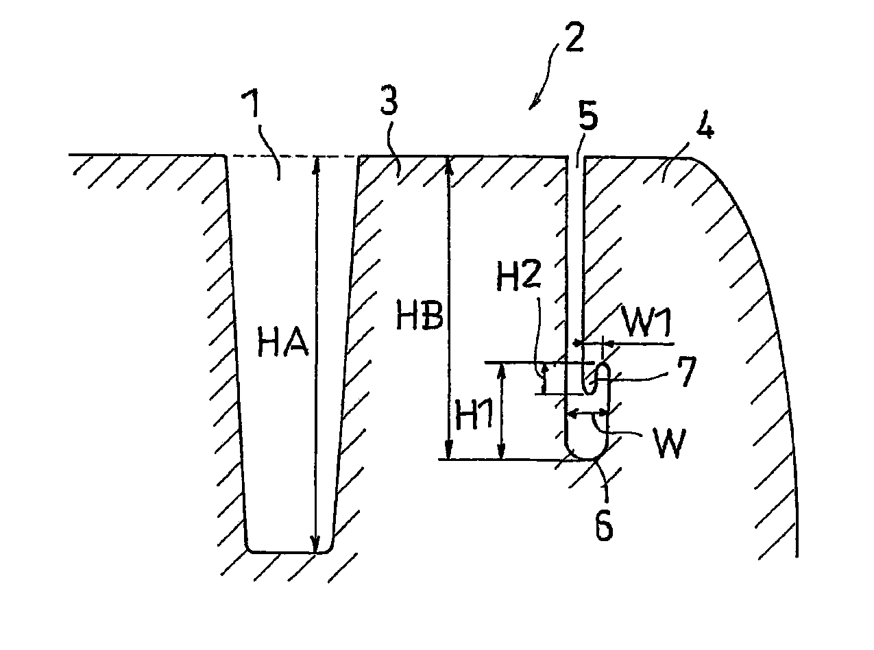
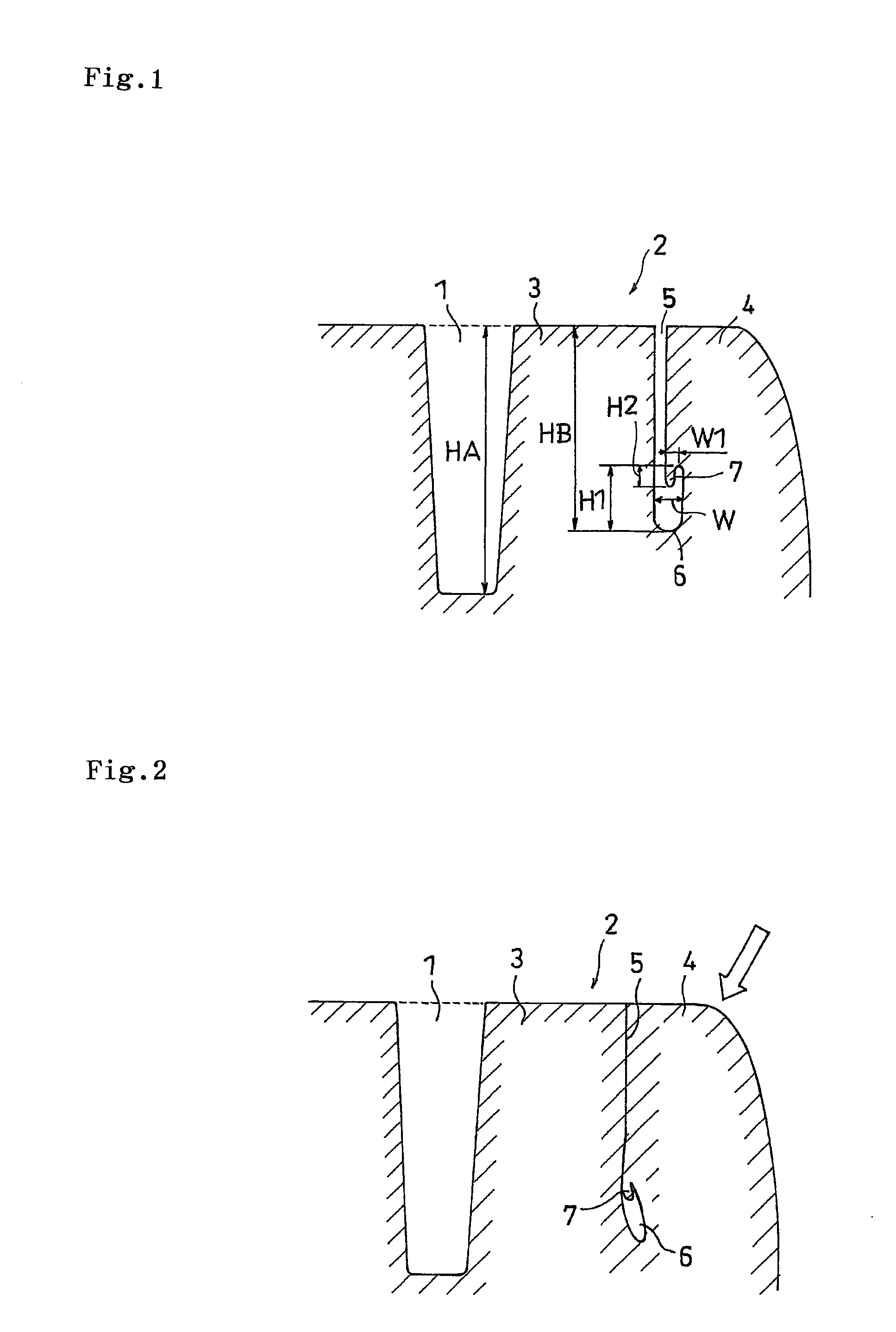
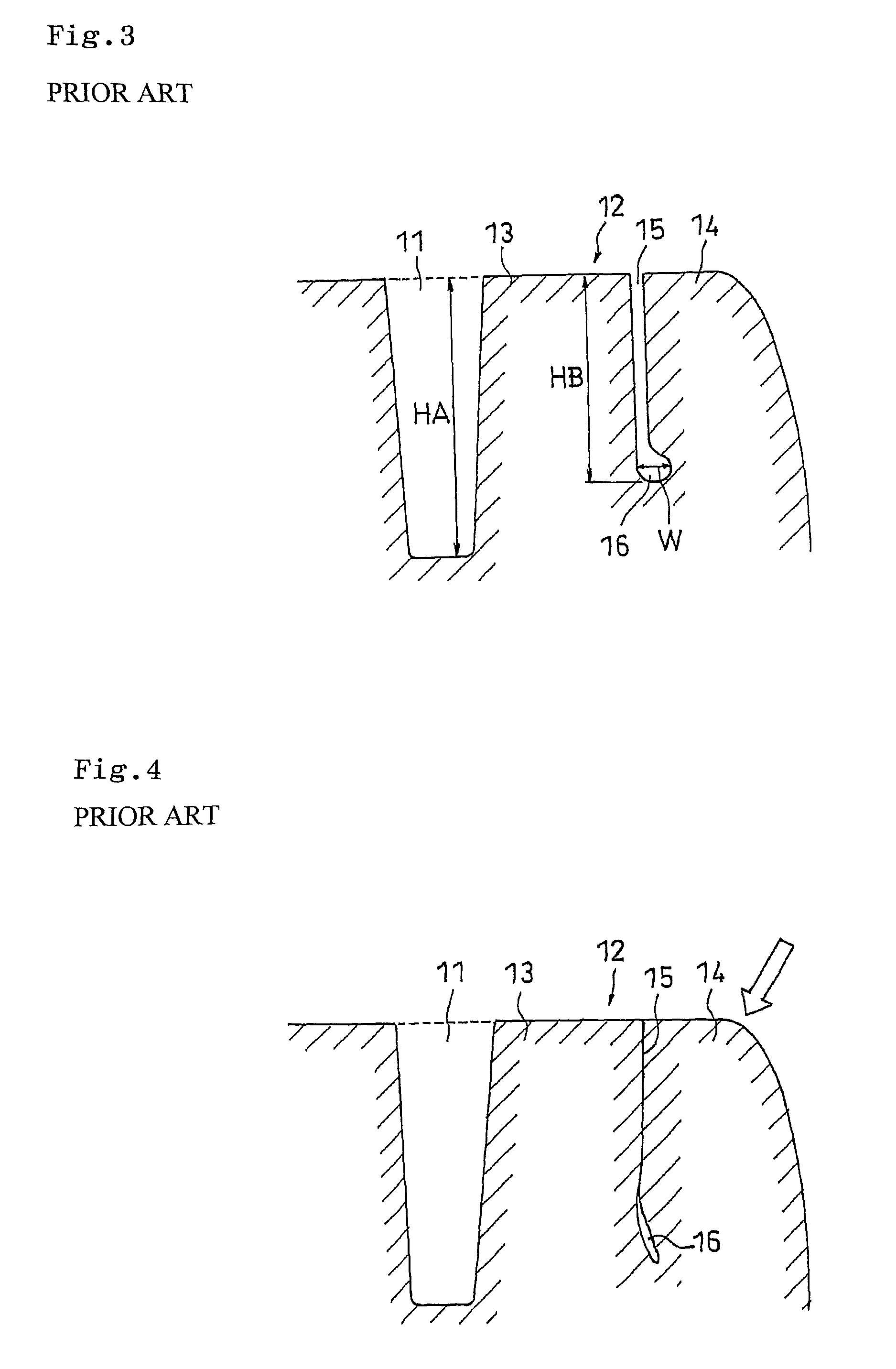
[0034]Pneumatic tires (size: 295 / 75 R22.5) formed with the thin groove 5 shown in FIG. 1 in the shoulder land portion 2, which have the same tread pattern as the pneumatic tire of the comparative Example 1 excepting the thin groove 15, wherein the maximum width W1 of the protruding portion 7, the maximum groove width W of the enlarged portion 6, the maximum height H1 of the enlarged portion 6 in the normal line direction of the tire, and the maximum height H2 of the protruding portion 7 in the normal line direction of the tire were set to the values listed in Table 1, were prepared. The above described evaluations were carried out. The depth HA of the main groove 1 was 14.7 mm; and the depth HB of the thin groove 5 was 14.9 mm. The results are shown in Table 1.

[0035]

TABLE 1ComparativeComparativeExample 1Example 2Example 1Example 2W1(mm)——1.02.5W(mm)3.07.03.04.0W1 / W——0.330.625H1(mm)——2.54.5H2(mm)——1.152.5Irregular wearACAAproof performanceGroove bottomCBAAcrack proofperformance

[0036]...


PUM


Abstract

A pneumatic tire comprising, on a tread face of the tire, a shoulder land portion extending in a circumferential direction of the tire, and a thin groove extending in the circumferential direction of the tire adjacent to a contact end of the shoulder land portion where comes into contact with the ground and segmenting the shoulder land portion into a main land portion located at the inner side thereof as viewed in the width direction of the tire and a sacrifice land portion located at the outer side thereof as viewed in the width direction of the tire, wherein the thin groove includes an enlarged portion extending in the circumferential direction of the tire in which a groove width thereof at groove bottom is enlarged toward the sacrifice land portion side only, and a protruding portion that protrudes toward the groove bottom side along the inner wall located at the sacrifice land portion side and extends in the circumferential direction of the tire.

Description

BACKGROUND OF THE INVENTION[0001]1. Field of the Invention[0002]The present invention relates to a pneumatic tire comprising, on a tread face of the tire, a shoulder land portion extending in a circumferential direction of the tire, and a thin groove extending in the circumferential direction of the tire adjacent to a contact end of the shoulder land portion where comes into contact with the ground and segmenting the shoulder land portion into a main land portion located at the inner side thereof as viewed in the width direction of the tire and a sacrifice land portion located at the outer side thereof as viewed in the width direction of the tire.[0003]2. Description of the Related Art[0004]Conventionally, in order to prevent irregular wear of tires, it is widely took measures that a tire is formed, on a tread surface, with a thin groove that extends in the circumferential direction of the tire adjacent to a contact end of the shoulder land portion where comes into contact with the ...

Claims


Application Information

Patent Timeline
Patent Type & Authority Patents(United States)
IPC IPC(8): B60C11/01B60C11/12
CPCB60C11/01B60C11/1281Y10S152/03
Inventor OHARA, MASAAKI
Owner TOYO TIRE & RUBBER CO LTD
Why Eureka
Try Eureka