
Self-leveling cementitious composition with controlled rate of strength development and ultra-high compressive strength upon hardening and articles made from same

a technology of self-leveling and cementitious composition, applied in the direction of climate sustainability, solid waste management, sustainable waste treatment, etc., can solve the problems of insufficient compressive strength to provide a high degree of resistance to ballistic and blast loads, high degree of resistance to mixing, and difficult processing in conventional manufacturing processes for making thin cement-based products and composites. , the effect of high degree of resistan

Active Publication Date: 2011-10-04
UNITED STATES GYPSUM CO +1
View PDF81 Cites 48 Cited by
  • Summary
  • Abstract
  • Description
  • Claims
  • Application Information

AI Technical Summary

Benefits of technology

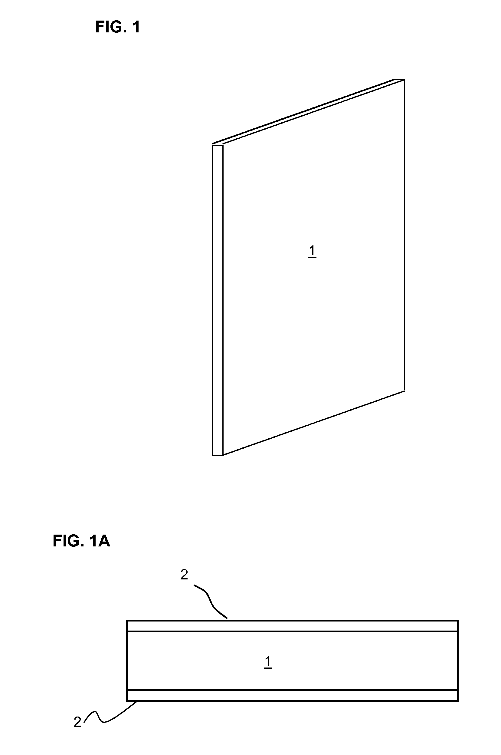
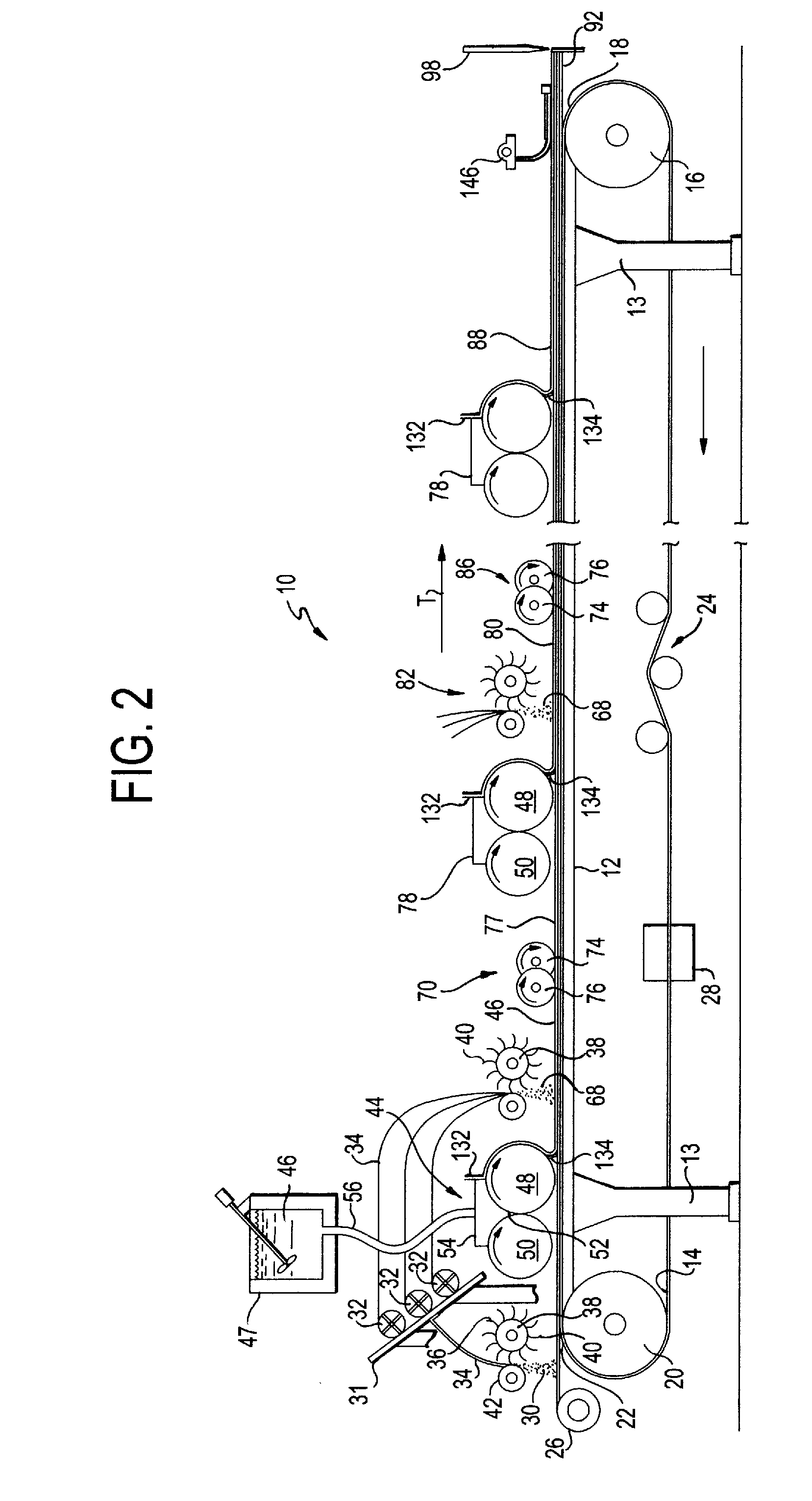
The present invention relates to a method for making a cementitious panel. The method involves depositing layers of chopped fiber and cement slurry on a carrier, passing them through an embedment device to embed the chopped fibers into the cement slurry layer, and then curing the panels. The resulting panels have a smooth surface and a thickness of about 0.50 in. The flow properties and self-leveling behavior of the cementitious compositions can be characterized using the slump test. The slump value of the cementitious slurries should be less than about 5 inches (12.7 cm) for efficient manufacturing. The influence of various raw material variables on the flow properties and self-leveling behavior can also be determined using the slump test.

Problems solved by technology

However, a drawback of such conventional panels is that they do not have sufficient compressive strength to provide a high degree of resistance to ballistic and blast loads and other severe impacts.
The stiff consistency makes these mixtures highly unworkable and extremely difficult to process in conventional manufacturing processes for making thin cement-based products and composites.

Method used


Image

  • Self-leveling cementitious composition with controlled rate of strength development and ultra-high compressive strength upon hardening and articles made from same
  • Self-leveling cementitious composition with controlled rate of strength development and ultra-high compressive strength upon hardening and articles made from same
  • Self-leveling cementitious composition with controlled rate of strength development and ultra-high compressive strength upon hardening and articles made from same

Examples


example 1

[0229]Slump was measured by pouring slurry into a 2 inch diameter cylinder that is 4 inches tall (open on each end and placed on end on a flat smooth surface) and screeding the top of the slurry off. This provides a set volume of slurry for every test. Then the cylinder was immediately lifted and the slurry rushed out the open bottom end of the cylinder. This act formed a circular “patty” of slurry. The diameter of this patty is measured in inches and recorded. More fluid slurry will typically result in a larger diameter patty.

[0230]TABLE 3 shows the influence of silica sand content as the inorganic mineral filler on slump of the cementitious mixtures. The other raw materials in the various mixtures were held constant. As the results show, the slump of the cementitious mixtures decreases with an increase in the silica sand content in the mixture.

[0231]Typical formulations for the mixtures in TABLE 3 through 7 are shown in the above discussed TABLE 1.

[0232]

TABLE 3MixtureInorganic Min...

example 2

[0233]TABLE 4 shows the influence of the particle size of silica sand on slump of the cementitious mixtures. Two types of silica sand were used, the first with a median particle size of about 200 microns and the second with a median particle size of about 10 microns. The other raw materials were maintained constant. As shown in the table, the slump of the cementitious mixtures decreased significantly with the use of finer silica sand in the composition.

[0234]

TABLE 4MixtureInorganic Mineral Filler TypeSlump in inches (cm)Mix 4Coarse Silica Sand with 2007 in. (17.8 cm)microns median particle size1Mix 5Fine Silica Sand with 10 microns2 in. (5.1 cm)median particle size21Coarse silica sand - US Silica F-55 unground silica2Fine silica sand - US Silica MIN-U-SIL 40 ground silica

example 3

[0235]TABLE 5 shows the influence of silica fume pozzolanic micro filler content on the slump of the cementitious mixture with all other raw materials maintained constant. It can be observed that the slump of the cementitious mixtures decreases with an increase in the content of silica fume in the mixture.

[0236]

TABLE 5MixtureSilica Fume Content1Slump in inches (cm)Mix 615%9.5 in. (22.8)Mix 725%  6 in. (15.2)Mix 835%  3 in. (7.6)1Silica Fume content expressed as a weight % of total cementitious materials, where Portland cement and Silica sand are considered as cementitious materials in the mixture. For example, Mix 6 contains 15 parts by weight silica fume and 85 parts by weight combined portland cement and silica sand.


PUM

PropertyMeasurementUnit
particle sizeaaaaaaaaaa
median particle sizeaaaaaaaaaa
compressive strengthaaaaaaaaaa

Abstract

A self-leveling cementitious mixture with excellent flow properties and which hardens with a controlled rate of strength development to an ultra-high compressive strength composite composition for use in making articles such as cementitious armor panel with ballistic and blast resistant properties including: a continuous phase resulting from the curing of an aqueous mixture, in the absence of silica flour, of inorganic cement binder, inorganic mineral filler having a particle size of about 150-450 microns, pozzolanic mineral filler, polycarboxylate based self-leveling agent and water. The cementitious mixture may include alkanolamine, such as triethanolamine, and acid or acid salt, such as tartaric acid. The cementitious composition may be reinforced with reinforcing fibers, e.g. glass fibers, in an amount of about 0.5-6.0% by volume of the overall cementitious composition. The fibers are uniformly dispersed in the cementitious composition before it is cured to form a final cementitious armor panel.

Description

CROSS REFERENCE TO RELATED APPLICATIONS[0001]This application claims the benefit of U.S. Provisional Application No. 61 / 033,212 filed Mar. 3, 2008, incorporated herein by reference, and is related to:[0002]U.S. Provisional Patent Application No. 61 / 033,240, entitled PROCESS OF MANUFACTURING CEMENT BASED ARMOR PANELS, filed Mar. 3, 2008;[0003]U.S. Provisional Patent Application No. 61 / 033,258, entitled CEMENT BASED ARMOR PANEL SYSTEM, filed Mar. 3, 2008;[0004]U.S. Provisional Patent Application No. 61 / 033,264, entitled CEMENT BASED LAMINATED ARMOR PANELS, filed Mar. 3, 2008;[0005]U.S. Patent Application No. 61 / 033,061, entitled TRANSPORTABLE MODULAR SYSTEM OF COMPONENTS FOR PHYSICAL PROTECTION, filed Mar. 3, 2008; and[0006]U.S. Patent Application No. 61 / 033,059, entitled TRANSPORTABLE MODULAR FRAME FOR HOLDING PANELS FOR PHYSICAL PROTECTION, filed Mar. 3, 2008;STATEMENT OF FEDERALLY SPONSORED RESEARCH[0007]The research work described here was supported under Cooperative Research and ...

Claims


Application Information

Patent Timeline
Patent Type & Authority Patents(United States)
IPC IPC(8): C04B24/26
CPCC04B28/02C04B28/04C04B14/42C04B14/48C04B16/06C04B20/008C04B24/04C04B24/122C04B24/2647C04B14/06C04B18/146C04B24/06C04B24/2658C04B40/0263C04B40/04C04B2201/52C04B2111/00974C04B2111/00629C04B2111/00103C04B2103/0088Y02W30/91
Inventor DUBEY, ASHISHCHAN, CESARNATESAIYER, KUMARDURST, BARTLEY P.KINNEBREW, PAMELA G.CUMMINS, TONEY K.BOONE, NICHOLASHEARD, WILLIAM F.ROTH, MICHAEL J.SLAWSON, THOMAS
Owner UNITED STATES GYPSUM CO
Learn More