
Electrode for a fuel cell, and a membrane-electrode assembly and fuel cell system comprising the same

a fuel cell and membrane-electrode technology, which is applied in the direction of cell components, cell component details, electrochemical generators, etc., can solve the problems of reducing the output voltage of the fuel cell, unable to endure the pressure added, and material breakage easily, so as to achieve easy hygroscopic regulation and improve the ability

Inactive Publication Date: 2011-09-13
SAMSUNG SDI CO LTD
View PDF70 Cites 1 Cited by
  • Summary
  • Abstract
  • Description
  • Claims
  • Application Information

AI Technical Summary

Benefits of technology

The nano-carbon fiber electrode substrate improves fuel cell efficiency and durability, maintaining desired moisture levels and reducing manufacturing complexity and costs by withstanding hot-pressing processes and optimizing catalyst usage.

Problems solved by technology

However, these materials have the disadvantage of breaking easily due to their low strength and are generally unable to endure the pressure added during the hot-pressing process necessarily required to fabricate a fuel cell.
In addition, they tend to lower the output voltage of a fuel cell because they cannot maintain appropriate humidity of a membrane-electrode assembly due to the low hygroscopic capability.
Accordingly, a method to improve these disadvantages has been attempted by setting separate humidifying equipment into a cell to maintain a predetermined hygroscopicity, but this method tends to raise the manufacturing cost and further complicates the fabrication procedures.
Another recent attempt has involved arranging a micro-porous layer (MPL) on the interface of the gas diffusion layer (GDL) adjoining the catalyst layer to maintain a predetermined hygroscopicity, but that approach has also failed to overcome the above disadvantages, while complicating fabrication procedures and raising the manufacturing cost.

Method used


Image

  • Electrode for a fuel cell, and a membrane-electrode assembly and fuel cell system comprising the same
  • Electrode for a fuel cell, and a membrane-electrode assembly and fuel cell system comprising the same

Examples


example 1

[0052]A slurry was prepared by mixing 20 parts by weight of Pt / C powder (Pt content of 20 wt %) and 13.4 parts by weights of Nafion™ in 66.6 parts by weight of a solvent mix of water and isopropyl alcohol (with a volume ratio of 4:1), treating the mixture with ultrasound for 30 minutes, and stirring it for 3 hours with a magnetic agitator.

[0053]The above slurry was coated on an electrode substrate composed of nano-carbon fiber with a pore diameter of 100 nm and dried to fabricate an anode and a cathode with a 60 μm-thick catalyst layer.

[0054]The above anode and cathode were stacked on both sides of Nafion112™ films and hot-pressed therewith together at a temperature of 120° C. for 3 minutes to fabricate a membrane-electrode assembly. Then, a unit cell was fabricated by connecting separators on both sides of the membrane-electrode assembly.

example 2

[0055]Another unit cell was fabricated by the same procedure as Example 1 except for using platinum to form a 30 μm-thick catalyst layer by a sputtering method.

experimental example 1

[0058]Humidified hydrogen and air were injected into the unit cells fabricated in the above Examples and Comparative Examples at a temperature of 70° C. and at a normal pressure and the voltages were measured. The results are given in the following Table 1.

[0059]

TABLE 1Voltage (V)CurrentComparativeComparativeDensity (A / cm2)Example 1Example 2Example 1Example 200.940.930.920.910.20.910.870.830.820.60.680.620.530.510.80.530.510.470.4210.470.440.360.31

[0060]As shown in the above Table 1, outputs of the unit cells fabricated according to Examples 1 and 2 of the present invention proved to be much better than those of Comparative Examples 1 and 2 fabricated by using conventional carbon cloth.

[0061]The above fuel cell has a higher efficiency in that it has excellent gas and water permeability, outstanding electron conductivity, and a low defect rate of products because it can endure the hot-rolling process due to an electrode substrate comprising nano-carbon fiber.


PUM

PropertyMeasurementUnit
pore sizeaaaaaaaaaa
diameteraaaaaaaaaa
thicknessaaaaaaaaaa

Abstract

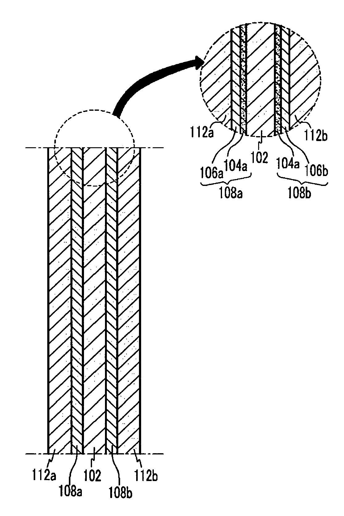
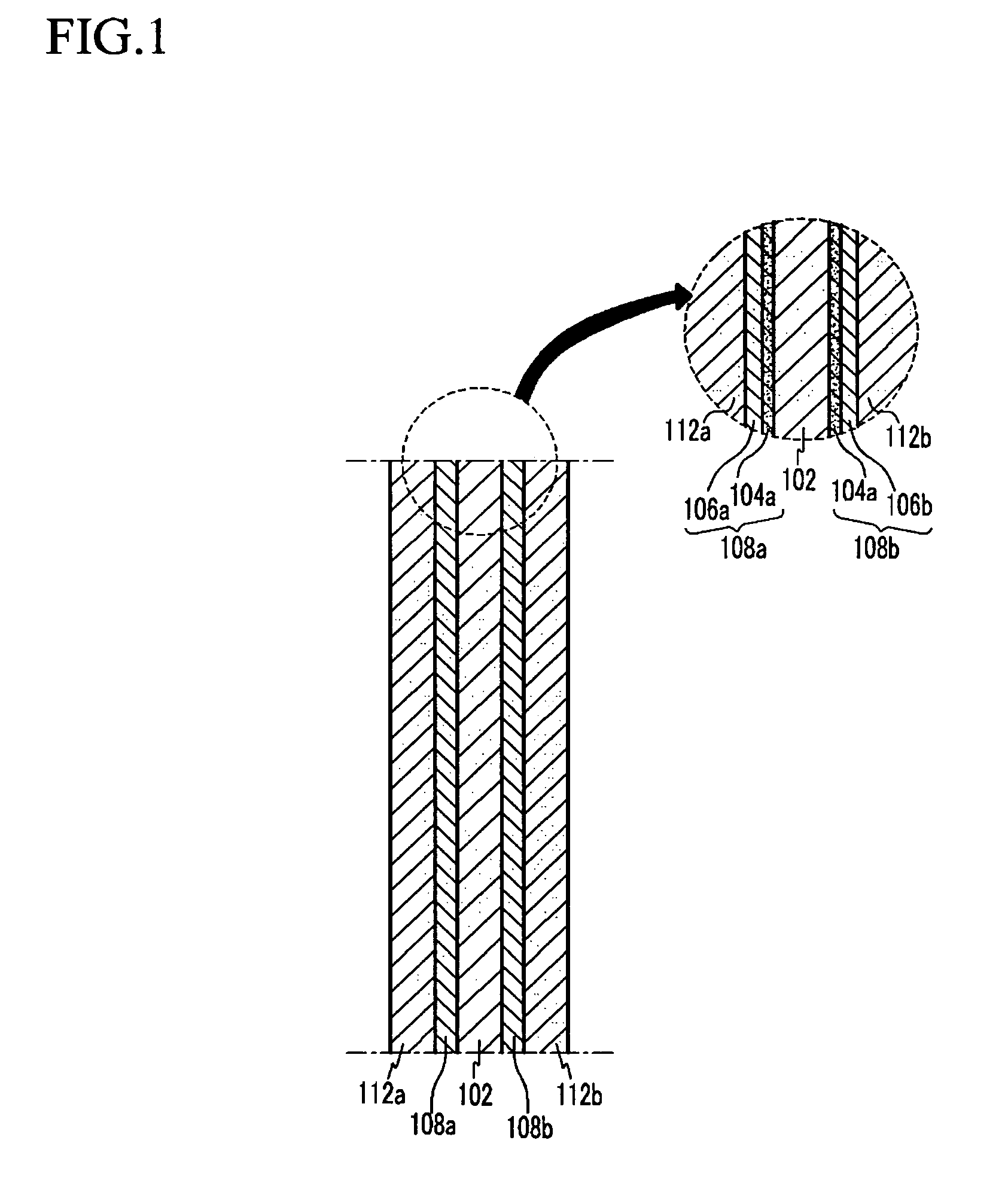
The present invention relates to an electrode for a fuel cell which includes an electrode substrate composed of nano-carbon fiber, with a catalyst layer formed on the electrode substrate. The electrode substrate has a better strength than an electrode substrate composed of a conventional carbonaceous material, and a pore size which can be controlled even though the composition for forming the catalyst layer may be coated in the form of a slurry.

Description

CROSS REFERENCE TO RELATED APPLICATION[0001]This application claims priority to and the benefit of Korean Patent Application No. 10-2004-0071669 filed in the Korean Intellectual Property Office on Sep. 8, 2004, the entire content of which is incorporated hereinto by reference.FIELD OF THE INVENTION[0002]The present invention relates to an electrode for a fuel cell, a membrane-electrode assembly for a fuel cell, and a fuel cell system comprising the same.BACKGROUND OF THE INVENTION[0003]An electrode for a fuel cell is equipped with a gas diffusion layer (GDL) and a catalyst layer. The gas diffusion layer generally uses a porous material to smoothly supply the catalyst later with fuel or oxidant. Exemplary of the commonly used porous materials include carbon paper, carbon cloth, and carbon felt.[0004]However, these materials have the disadvantage of breaking easily due to their low strength and are generally unable to endure the pressure added during the hot-pressing process necessari...

Claims


Application Information

Patent Timeline
Patent Type & Authority Patents(United States)
IPC IPC(8): H01M2/14H01M8/04H01M4/90
CPCB82Y30/00H01M4/8605H01M4/92H01M4/926Y02E60/522Y02E60/50H01M4/96H01M4/86H01M4/90
Inventor NOH, HYUNG-GON
Owner SAMSUNG SDI CO LTD
Learn More