
Integrated circuit memory with word line driving helper circuits

a technology of integrated circuit memory and word line signal, which is applied in the direction of electric variable regulation, static storage, instruments, etc., can solve the problems of word line signal being too slow to reach its asserted values, small process geometries tend to suffer from more chip-to-chip variation and even significant amounts of variation

Active Publication Date: 2011-09-06
ARM LTD
View PDF6 Cites 4 Cited by
  • Summary
  • Abstract
  • Description
  • Claims
  • Application Information

AI Technical Summary

Benefits of technology

This approach speeds up the word line signal propagation, improving memory operation efficiency and reducing the likelihood of incorrect operations while minimizing circuit overhead, allowing for higher memory density and reduced power consumption.

Problems solved by technology

As process geometries have become smaller and memory densities higher, problems have arisen in propagation of the word line signal through the array.
The problems of the word line signal being too slow to reach its asserted values are made worse when operating at lower operating voltages.
Furthermore, the smaller process geometries tend to suffer from more chip-to-chip variation and even significant amounts of variation due to process, voltage and temperature within an individual chip.
This coupling with the bit lines also becomes worse as process geometries become smaller.
These factors tend to combine to slow the speed with which the word line signal reaches the asserted value and accordingly slow the operation of the memory since an increased amount of time has to be allowed between accesses in order to allow sufficient time to be sure that the word line signal has properly reached its asserted value so that the access required will have been properly performed.
The technique of providing word line drivers at each end of the word line does address the above problems, but suffers from the disadvantage that a second set of word line driver circuitry and associated decoders and control circuitry need to be provided and this consumes an undesirable amount of circuit overhead.
In turn, this adversely affects the circuit density of the memory as a whole and tends to increase its cost and power consumption.

Method used


Image

  • Integrated circuit memory with word line driving helper circuits
  • Integrated circuit memory with word line driving helper circuits
  • Integrated circuit memory with word line driving helper circuits

Examples


Embodiment Construction

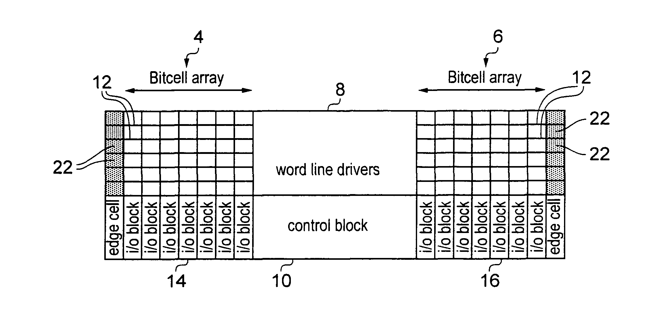
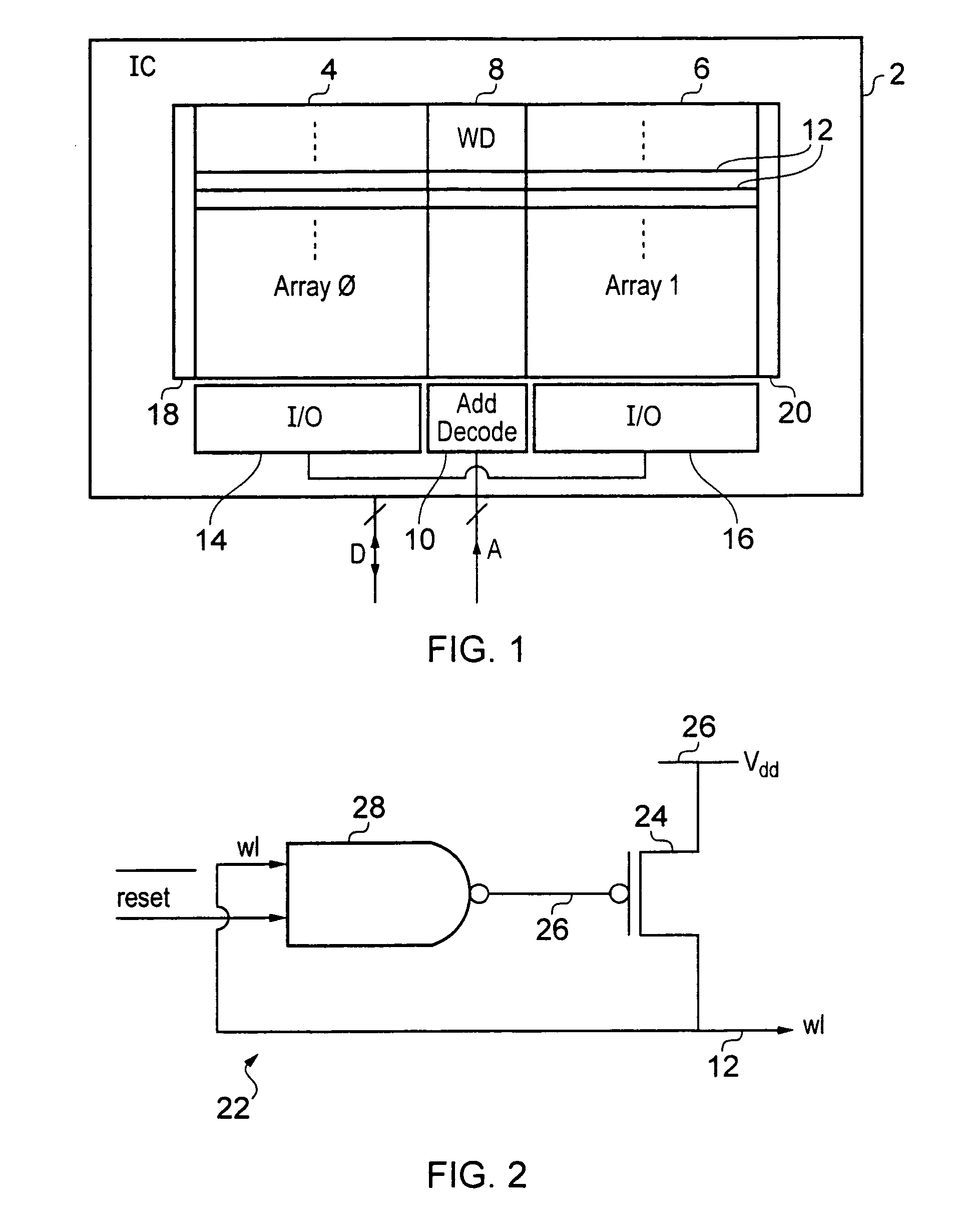
[0060]FIG. 1 shows an integrated circuit memory 2 including a first array of bit cells 4 and a second array of bit cells 6. Word line driver circuitry 8 is disposed between the first array 4 and the second array 6. Address decoder circuitry 10 operating in conjunction with the word line driver circuitry 8 serves to decode an address input to the integrated circuit memory 2 and active one of the word lines 12 running through the first array 4 and the second array 6. A data write or data read operation is then performed to the appropriate array 4, 6 via input output circuitry 14, 16.

[0061]As process geometries and operating voltages become smaller and the effects of process, voltage and temperature variation across an integrated circuit 2 become larger, the finite resistance and capacitance of the word lines 12 becomes significant and there is a delay in a word line signal reaching its full asserted value and this delay increases the further along the word line 12 the signal must prop...


PUM


Abstract

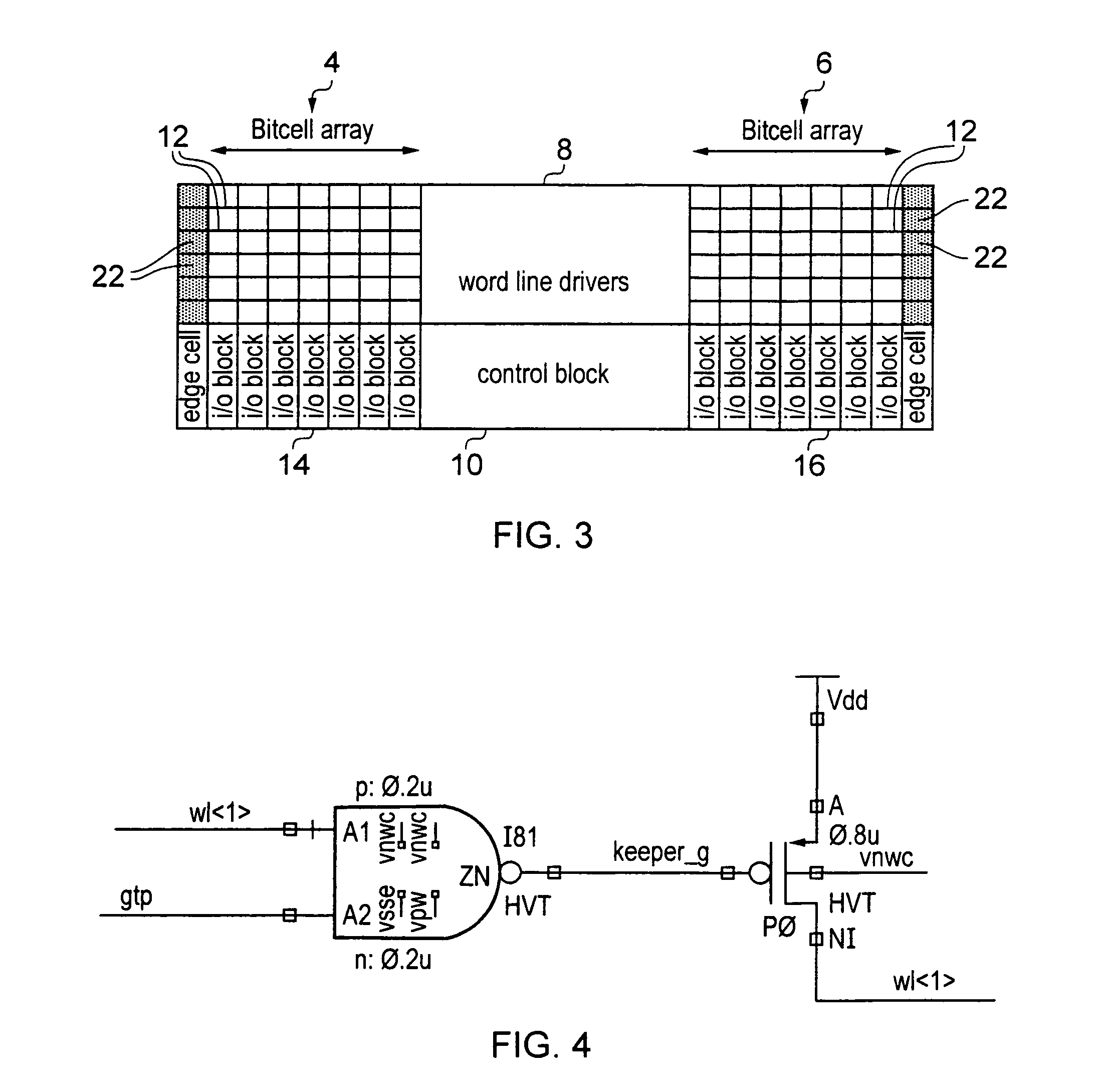
An integrated circuit memory 2 incorporates a first array of bit cells 4 and a second array of bit cells 6 with word line driver circuitry 8 disposed therebetween. Word line helper circuitry 18, 20 is disposed at the opposite edges of the array 4, 6 to the word line driver circuitry 8. The helper circuitry is responsive to the word line signal on a word line 12 being driven towards an asserted value to switch on and further drive the word line signal towards the asserted value. The helper circuitry is switched off by a global reset signal, which may be a self-timed global reset signal.

Description

BACKGROUND OF THE INVENTION[0001]1. Field of the Invention[0002]This invention relates to the field of integrated circuit memories. More particularly, this invention relates to the driving of word line signals within integrated circuit memories.[0003]2. Description of the Prior Art[0004]It is known to provide integrated circuit memories comprising arrays of bit cells. Word lines carrying word line signals run through these arrays and are used to select a row of bit cells to be accessed. An address of a memory location is input to an integrated circuit memory which decodes this address and determines which word line through an array of bit cells should be driven to an asserted value so that the corresponding row of bit cells may be accessed. As process geometries have become smaller and memory densities higher, problems have arisen in propagation of the word line signal through the array. The word line itself has a finite resistance and capacitance such that it acts as a distributed ...

Claims


Application Information

Patent Timeline
Patent Type & Authority Patents(United States)
IPC IPC(8): G11C11/24
CPCG11C8/08
Inventor YEUNG, GUSSHANMUGAM, AMARNATHCHONG, YEW KEONGWIATROWSKI, JACEK
Owner ARM LTD
Learn More