
Electronic apparatus with hidden antenna

a technology of electronic equipment and hidden antennas, applied in the direction of antenna details, slot antennas, antennas, etc., can solve the problems of restricting the miniaturization of electronic equipment, and achieve the effect of reducing the overall fabrication cos

Active Publication Date: 2011-08-30
HTC CORP
View PDF7 Cites 17 Cited by
  • Summary
  • Abstract
  • Description
  • Claims
  • Application Information

AI Technical Summary

Benefits of technology

The patent text describes an electronic apparatus with a hidden antenna that uses a metal frame for receiving / transmitting electromagnetic signals. This eliminates the need for a separate space for the antenna, reducing fabrication costs and allowing for miniaturization of the apparatus. The metal frame is engaged with the upper and lower housings of the apparatus, forming a cavity for accommodating a substrate. The substrate includes a metal surface that is electrically connected to the metal frame, allowing for efficient use of the frame for transmitting signals. The notch in the metal frame is passed through two adjacent side walls and includes a feeding terminal, a first shorting terminal, and a second shorting terminal, creating a half wavelength loop antenna. This allows for effective utilization of the frame for signal transmission. Overall, the patent proposes a solution for incorporating a hidden antenna into an electronic apparatus, reducing fabrication costs and allowing for miniaturization.

Problems solved by technology

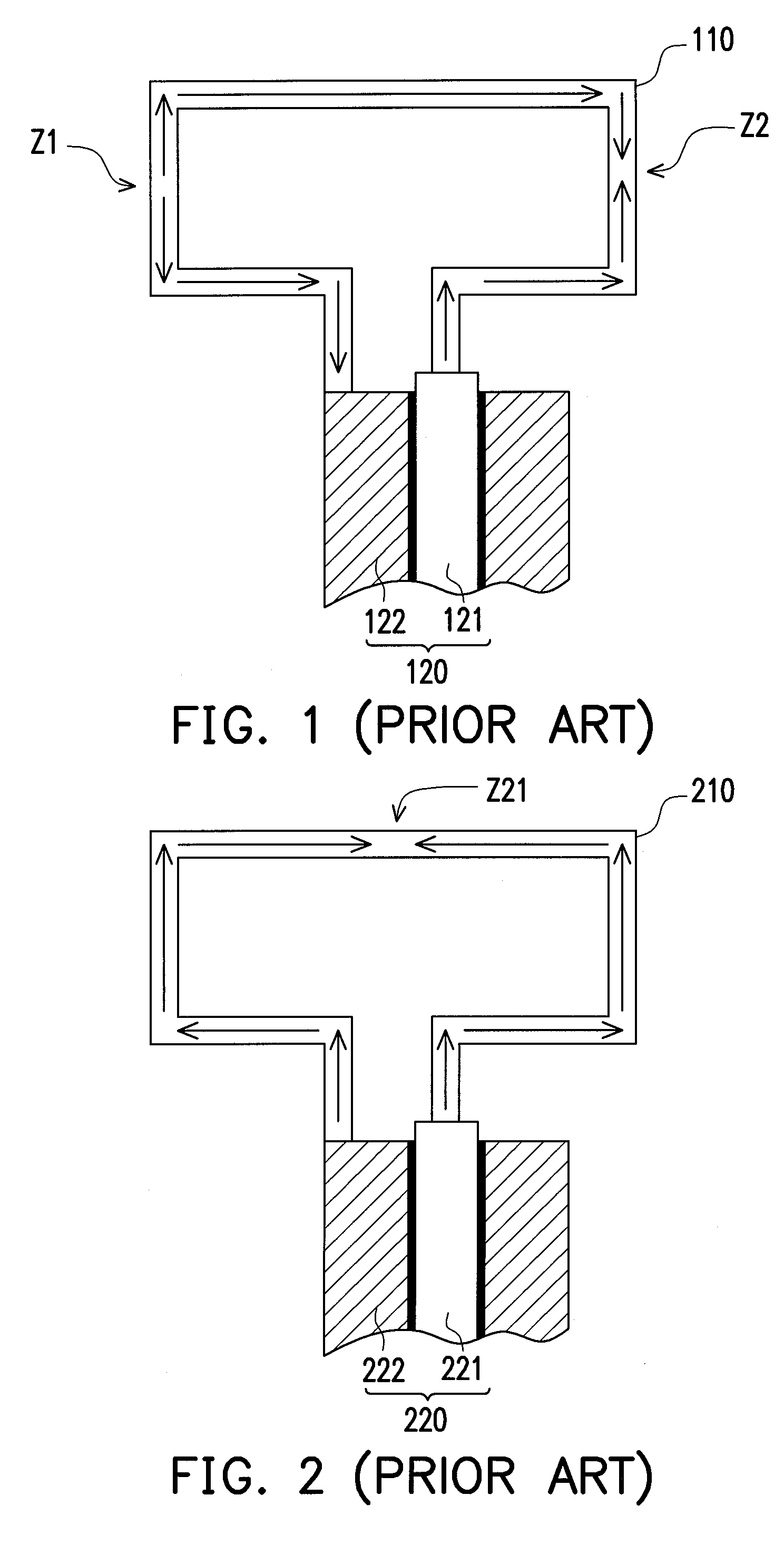
However, because the loop antenna adopts a full wavelength mode for operation, it would occupy a larger space within the electronic apparatus, and thus restricting the miniaturization of the electronic apparatus.

Method used


Image

  • Electronic apparatus with hidden antenna
  • Electronic apparatus with hidden antenna
  • Electronic apparatus with hidden antenna

Examples


Embodiment Construction

[0032]Reference will now be made in detail to the present preferred embodiments of the invention, examples of which are illustrated in the accompanying drawings. Wherever possible, the same reference numbers are used in the drawings and the description to refer to the same or like parts.

[0033]The application is featured in that a metal frame is employed for reinforcing the structure of an electronic apparatus. The metal frame is adapted for receiving and transmitting an electromagnetic signal. The electronic apparatus with a hidden antenna is illustrated hereafter without restricting the electronic apparatus of being PDA cell phone, smart phones or a satellite navigator.

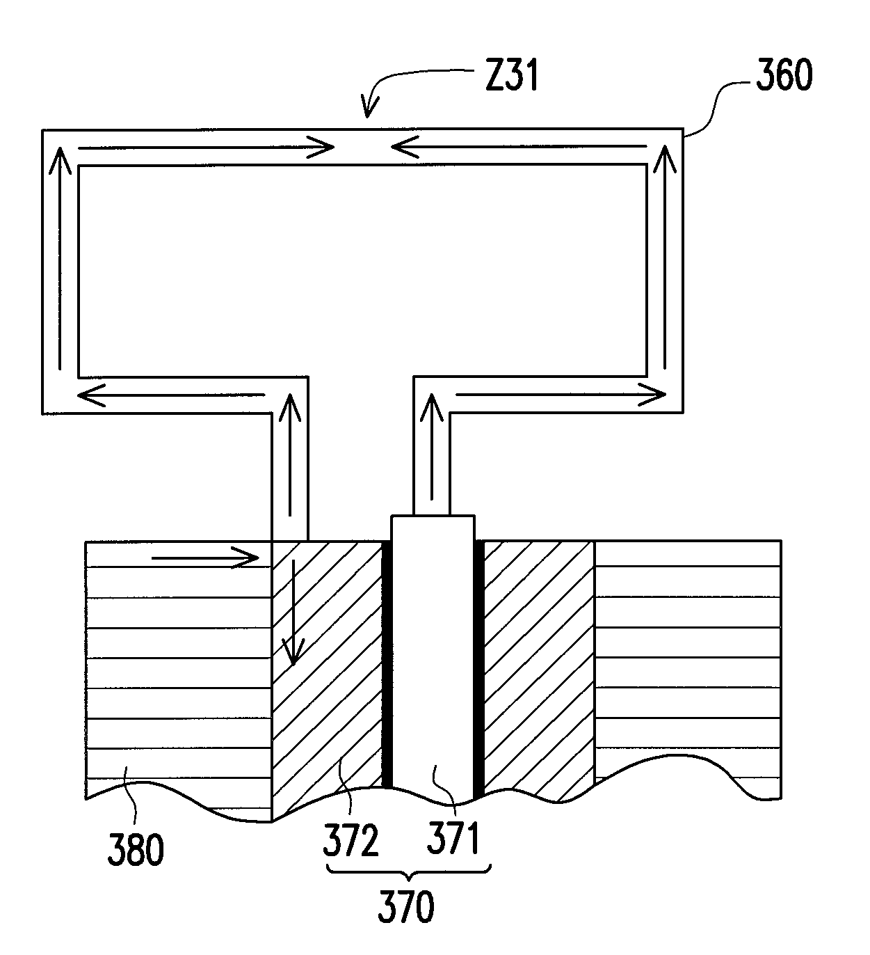
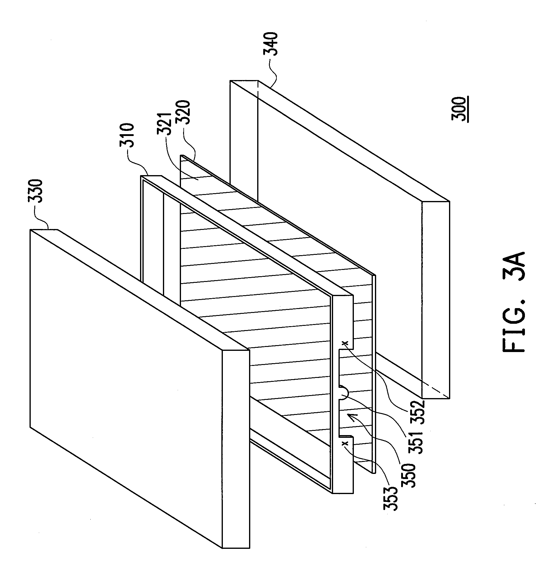
[0034]FIG. 3A is a schematic structural diagram illustrating a theory with a hidden antenna according to an embodiment of the present invention. Referring to FIG. 3A, the electronic apparatus 300 includes a metal frame 310, a substrate 320 and a metal lower housing 340. The substrate includes a metal surface 321. The...


PUM


Abstract

An electronic apparatus with a hidden antenna comprises a metal frame and a substrate. The metal frame comprises a plurality of side walls and a notch is passed through at least one side wall. A feeding terminal is configured at a bottom side of the notch. A first shorting terminal and a second shorting terminal are configured at two lateral sides of the notch. A metal surface of the substrate is electrically connected to the first shorting terminal, the second shorting terminal and the side walls, and the notch is faced to the substrate. The metal frame receives or transmits an electromagnetic signal, and delivers the electromagnetic signal over the feeding terminal, and a length of the bottom side of the notch is one half of a wavelength of the electromagnetic signal.

Description

CROSS-REFERENCE TO RELATED APPLICATION[0001]This application-claims the priority benefit of Taiwan application serial no. 96151567, filed on Dec. 31, 2007. The entirety of the above-mentioned patent application is hereby incorporated by reference herein and made a part of this specification.BACKGROUND OF THE INVENTION[0002]1. Technology field[0003]The application generally relates to an electronic apparatus with a hidden antenna, and more particularly, to an electronic apparatus including a metal frame of a part of housing for transmitting / receiving electromagnetic signals.[0004]2. Description of Related Art[0005]Currently, wireless communication has become a more popular choice for human beings to communicate with each other. Correspondingly, there have been developed many kinds of wireless communication apparatuses, such as smart cell phones, multimedia players, personal digital assistants (PDAs), and satellite navigators. Almost all of the electronic apparatus capable of wireless...

Claims


Application Information

Patent Timeline
Patent Type & Authority Patents(United States)
IPC IPC(8): H01Q1/24
CPCH01Q1/2266H01Q1/243H01Q13/10
Inventor TENG, PEI-LINGCHEN, KUO-CHENG
Owner HTC CORP
Learn More