
Personal standing platform for motorized wheel chair

Active Publication Date: 2011-08-30
2001 BYRON L CHAPMAN & JUDI A CHAPMAN REVOCABLE TRUST
View PDF13 Cites 31 Cited by
  • Summary
  • Abstract
  • Description
  • Claims
  • Application Information

AI Technical Summary

Benefits of technology

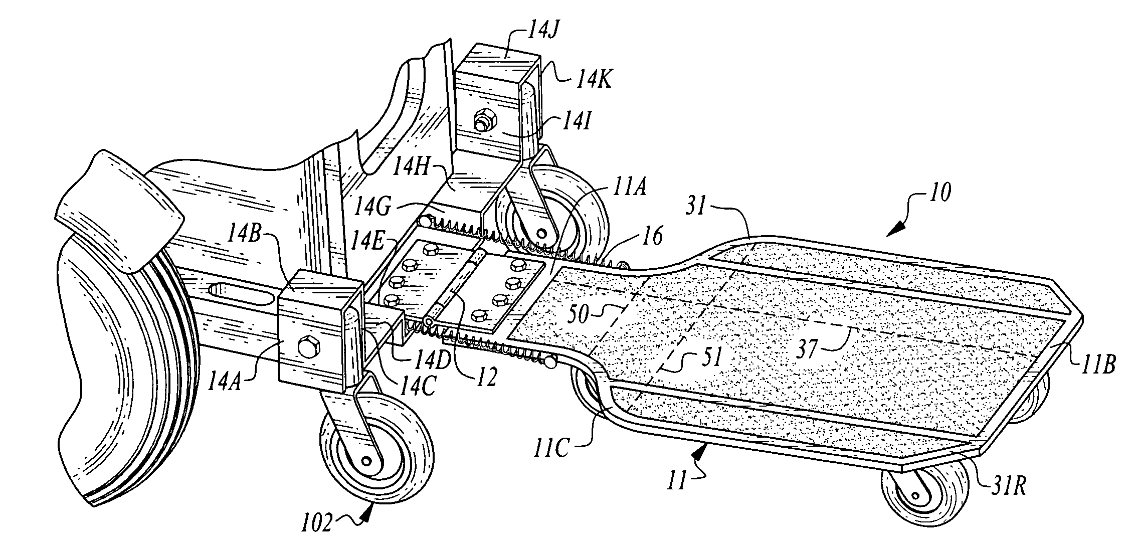
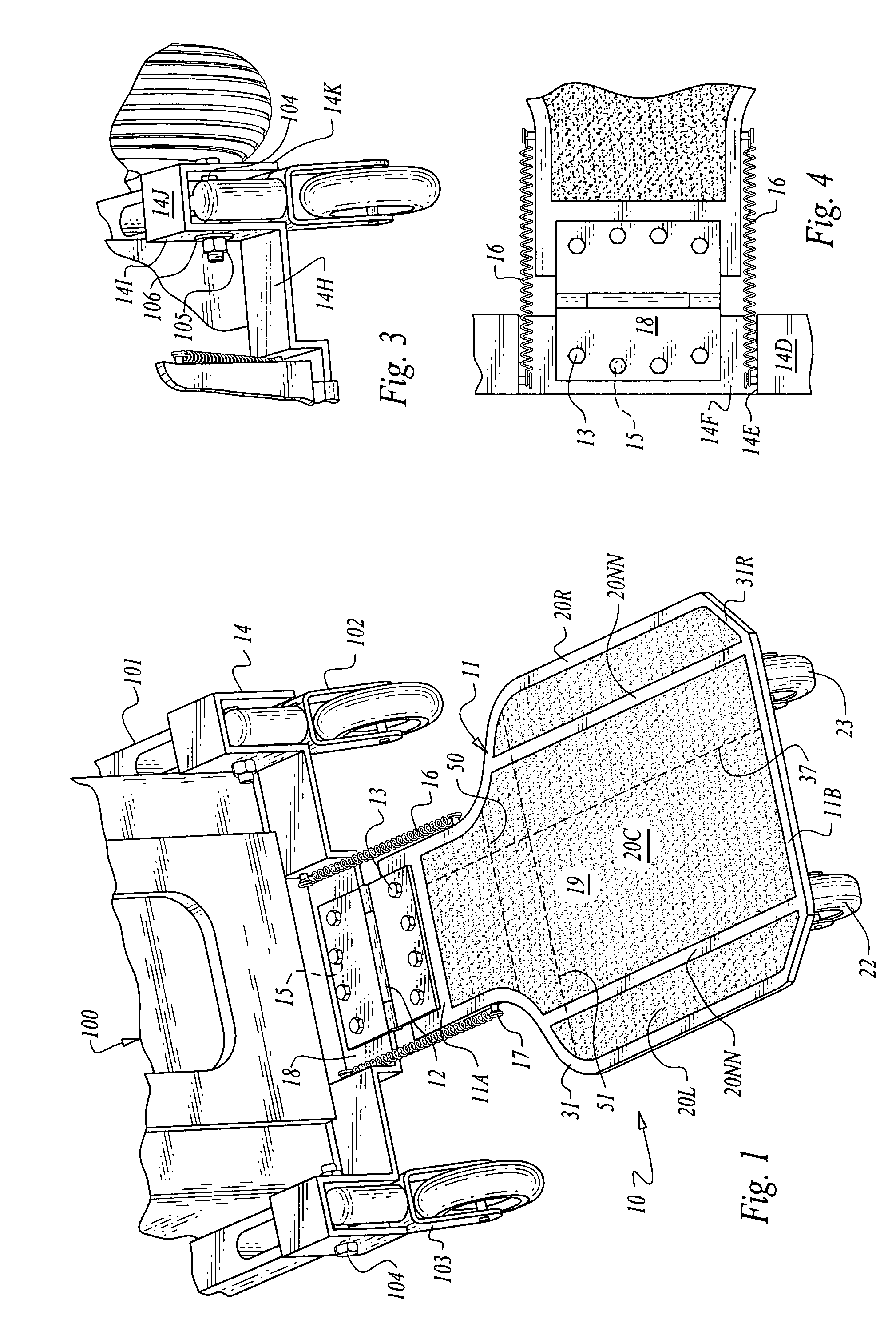
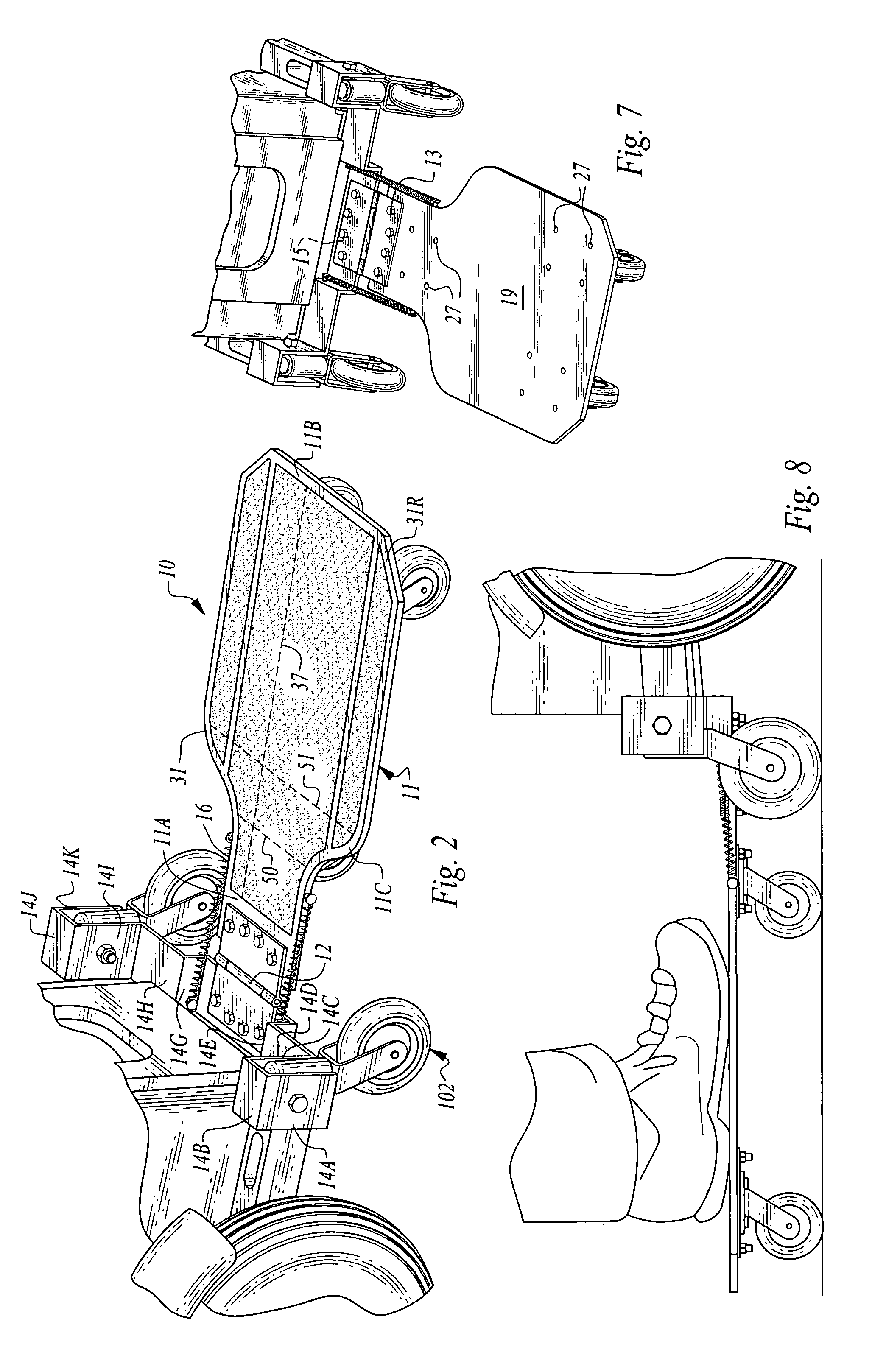
[0008]There is disclosed a releasably detachable passenger standing platform that attaches behind a motorized wheelchair or scooter onto the mounting means for the stabilizer wheels. These are the little wheels mandated to prevent the wheelchair or scooter from tipping backward on a hill or for some other reason when the load becomes unbalanced. The platform may be tilted up when not in use The platform has 2 trailing swivel casters and one leading centrally disposed swivel caster mounted to the underside of a rearwardly elongated platform sized to accommodate an adult person. The ability to ride short or long distances on the standing platform permits the companion, spouse, care giver or child of the vehicle operator to maintain the pace of the vehicle operator for extended periods of time.
[0012]It is fourth object to provide a PSP that will not buckle under the stress of being towed with a passenger in place, at speeds up 10 mph, by a motorized vehicle.
[0013]It is a fifth object to provide a “PSP” for a motorized vehicle that permits the operator of the motor vehicle, to maintain his / her operating speed.

Problems solved by technology

When a person is walking side by side with a motorized wheelchair operating at full speed, the person walking may have difficulties in keeping up with the speed of the wheelchair, therefore is under a high degree of stress when they have to keep up with the speed of the motorized wheelchair and the distance traveled.
There have been previous inventions of a standing platform to be attached to the back of a powered wheelchair, however, such platforms are only equipped with limited number of wheels (two or less).
If the rear wheels are poorly positioned at the rear end of the platform and no wheel in the front of the platform, the weight of the standing person would deform the platform and cause a warping or deformation in the rear of the platform and increased weight on the tongue of the platform that connects to the rear of the wheelchair, eventually disabling the mobility of the standing platform.

Method used


Image

  • Personal standing platform for motorized wheel chair
  • Personal standing platform for motorized wheel chair
  • Personal standing platform for motorized wheel chair

Examples


Embodiment Construction

[0025]Let us first turn to FIG. 1, where the passenger standing platform, the invention 10 is seen attached to a mobility vehicle 100, here a motorized wheelchair of a conventional nature. Such chairs are sold by several vendors, the most popular brand of which is Quickee. All elements of the invention will be cast in 2 digit numbers while those of the mobility vehicle will be in the 3 digit series.

[0026]The device 10 includes a platform base 11 that is configured like a ping pong paddle in that it has a forward narrower section 11A and a wider elongated section 11B connected by a trapezoidal intermediate section 11C. See FIG. 2, wherein imaginary lines of demarcation for the intermediate section 11C are set out by dashed lines 50 and 51. Rear section 11B may have square corners, chamfered corners, or tapered corners as shown here and designated 31R in FIGS. 1 & 2. While shown with oblique rounded or chamfered rear corners for the rear section 11B, the corners need not be so configu...


PUM


Abstract

A passenger standing platform for attachment to a mobility vehicle that provides improved support for the rider, increased weightload, and easy mountability and storage capability, The unit has a paddle shape platform base with 3 fully rotating caster assemblies attached to its underside in a triangular configuration and a non-skid mat attached to its obverse side. The platform base is hingedly attached to a mount plate that connects to the mobility vehicle, and is retained in a non-use generally vertical position off the ground by a pair of spaced coil springs attached at opposite ends to the mount plate and to the platform base.

Description

FIELD OF THE INVENTION[0001]The invention relates to a releasably detachable wheelchair attachment and more particularly to a passenger carrying platform supported by three spaced swivel casters, none of which are connected to any other caster.KNOWN PRIOR ART[0002]Andes, U.S. Pat. No. 6,443,252 was issued on Sep. 3, 2002. The device of the only prior art patent known to applicant lacks the sophistication of the instant device. It has only two wheels, mounted on an axle, and as such, the wheelchair occupant must take special care in both making left and right turns, and especially when backing up. The backing up experience either with or without a passenger on the platform is akin to backing up a truck or car with a fixed axle trailer attached. Not for the faint of heart.[0003]In addition to Andes, the axle that carries the two wheels is disposed beneath the rear of the platform such that when the platform is occupied, there could arise a warping or deformation of the platform, due t...

Claims


Application Information

Patent Timeline
IPC IPC(8): B60K1/00B62D63/00
CPCA61G5/10A61G2005/1094A61G5/1094
Inventor CHAPMAN, JUDI
Owner 2001 BYRON L CHAPMAN & JUDI A CHAPMAN REVOCABLE TRUST
Learn More