Charging device, process cartridge, image forming apparatus, and toner
a technology of process cartridges and charging devices, which is applied in the direction of corona discharge, shafts and bearings, instruments, etc., can solve the problems of damage to the photoconductor surface, increased contamination of the charging roller surface, and remaining toner after the toner image transfer adhering to the charging roller
- Summary
- Abstract
- Description
- Claims
- Application Information
AI Technical Summary
Benefits of technology
Problems solved by technology
Method used
Image
Examples
example 2
of Charging Roller
[0276]The resistance of the protection layer is 4×10¹⁰ ohm-cm, and the thickness is about 10 micrometers. The resistance adjustment layer was formed by covering with injection molding the composite which blended and created the high molecular compound (“reorekkusu A-1720” from “dai-ichi kogyo seiyaku” Co.) 30 weight parts of ion conductivity which contains the fourth class ammonium-salt group to the ABS-plastics (“GR-1500” from “denki kagaku kogyo” Co.) 100 weight parts to the peripheral surface of the roller base made from stainless steel with a diameter of 8 mm. The volume resistivity value of the composite is 1×10⁸ ohm-cm.
[0277]Next, the charging roller (2) with a diameter of 12 mm is produced by applying to the surface of the resistance adjustment layer the mixture which includes the polyamide resin (“daiamido T-171” from “daiseruhyurusu” Co.) and the carbon black (it is the 10% of the weight to the total solid), and forming the protection layer in it. The res...
example 1
of Charging Cleaning Component
[0278]The charging cleaning component the periphery side of the example 1 of 5-mm diameter core metal is made to carry out heating compression of the layer which includes the melamine resin foam (“basotekuto” from BASF A.G.), and it sticks on it with adhesive. After the adhesion, the charging cleaning component (1) of the profile of roller with an outside diameter of 8.5 mm is produced by forming so that it may become 1.75 mm in thickness by carrying out the barrel polishing.
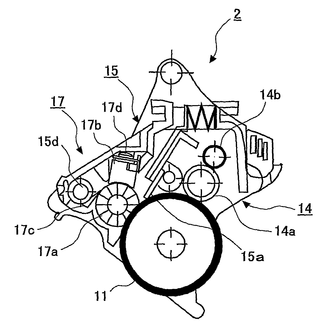
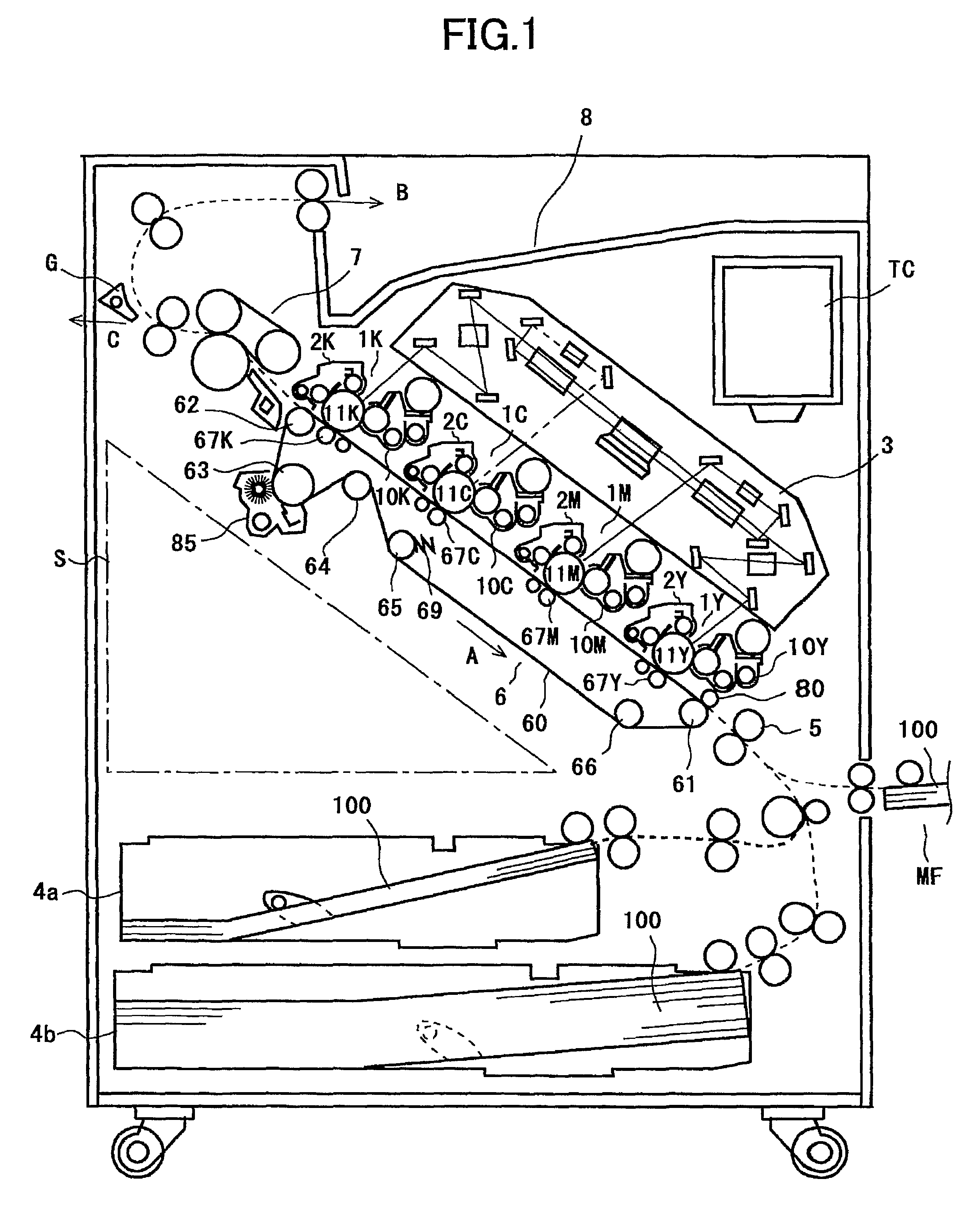
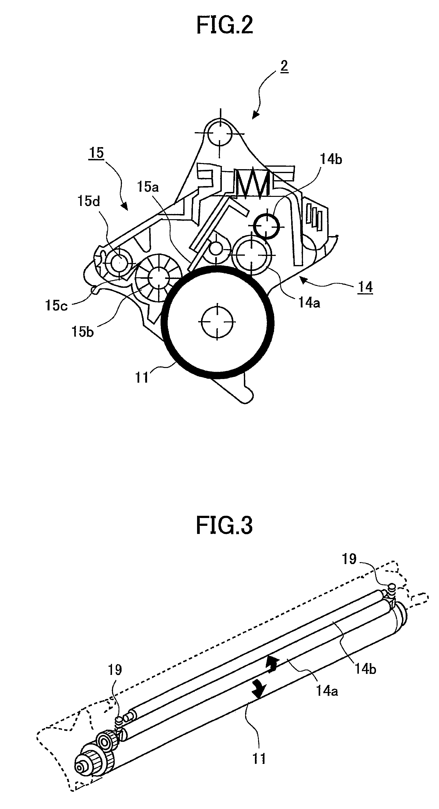
[0279]Next, the charging roller (1) produced as mentioned above by the group as shown in FIG. 1 as charging roller 14a, or (2) are disposed. The charging cleaning component (1) is disposed as the charging cleaning component 14b. The spacer tape is stuck on the non-image region of the shaft-orientations both ends of charging roller 14a.
[0280]The charging roller 14a is installed such that the gap between the charging roller 14a and the photoconductor drum 11 is set to 50 micrometers....
PUM
 Abstract
Description
Claims
Application Information
 - R&D
- Intellectual Property
- Life Sciences
- Materials
- Tech Scout
- Unparalleled Data Quality
- Higher Quality Content
- 60% Fewer Hallucinations
Browse by: Latest US Patents, China's latest patents, Technical Efficacy Thesaurus, Application Domain, Technology Topic, Popular Technical Reports.
© 2025 PatSnap. All rights reserved.Legal|Privacy policy|Modern Slavery Act Transparency Statement|Sitemap|About US| Contact US: help@patsnap.com


