Microwave circuit assembly comprising a microwave component suspended in a gas or vacuum region

a technology of micro-wave circuits and components, applied in waveguides, electrical devices, waveguides, etc., can solve the problems of reducing the production cost of bonded assemblies, exhibiting relatively high microwave loss, and reducing so as to reduce the thickness of an area.

Inactive Publication Date: 2011-08-16
BAE SYSTEMS PLC
View PDF12 Cites 7 Cited by
  • Summary
  • Abstract
  • Description
  • Claims
  • Application Information

AI Technical Summary

Benefits of technology

[0021]The method may further include reducing a thickness of an area of the LCP supporting layer, e.g. an area

Problems solved by technology

A disadvantage associated with such assemblies when higher performance is required is that they exhibit relatively high microwave loss.
Thus, the volume between the ground planes can mainly include air, which results in lower levels of microwave loss.
However,

Method used


Image

  • Microwave circuit assembly comprising a microwave component suspended in a gas or vacuum region
  • Microwave circuit assembly comprising a microwave component suspended in a gas or vacuum region
  • Microwave circuit assembly comprising a microwave component suspended in a gas or vacuum region

Examples


Embodiment Construction

[0036]Exemplary embodiments of the present invention will now be described in more detail, by way of example only, with reference to the accompanying drawings in which identical or corresponding parts are provided with the same reference numerals in the figures.

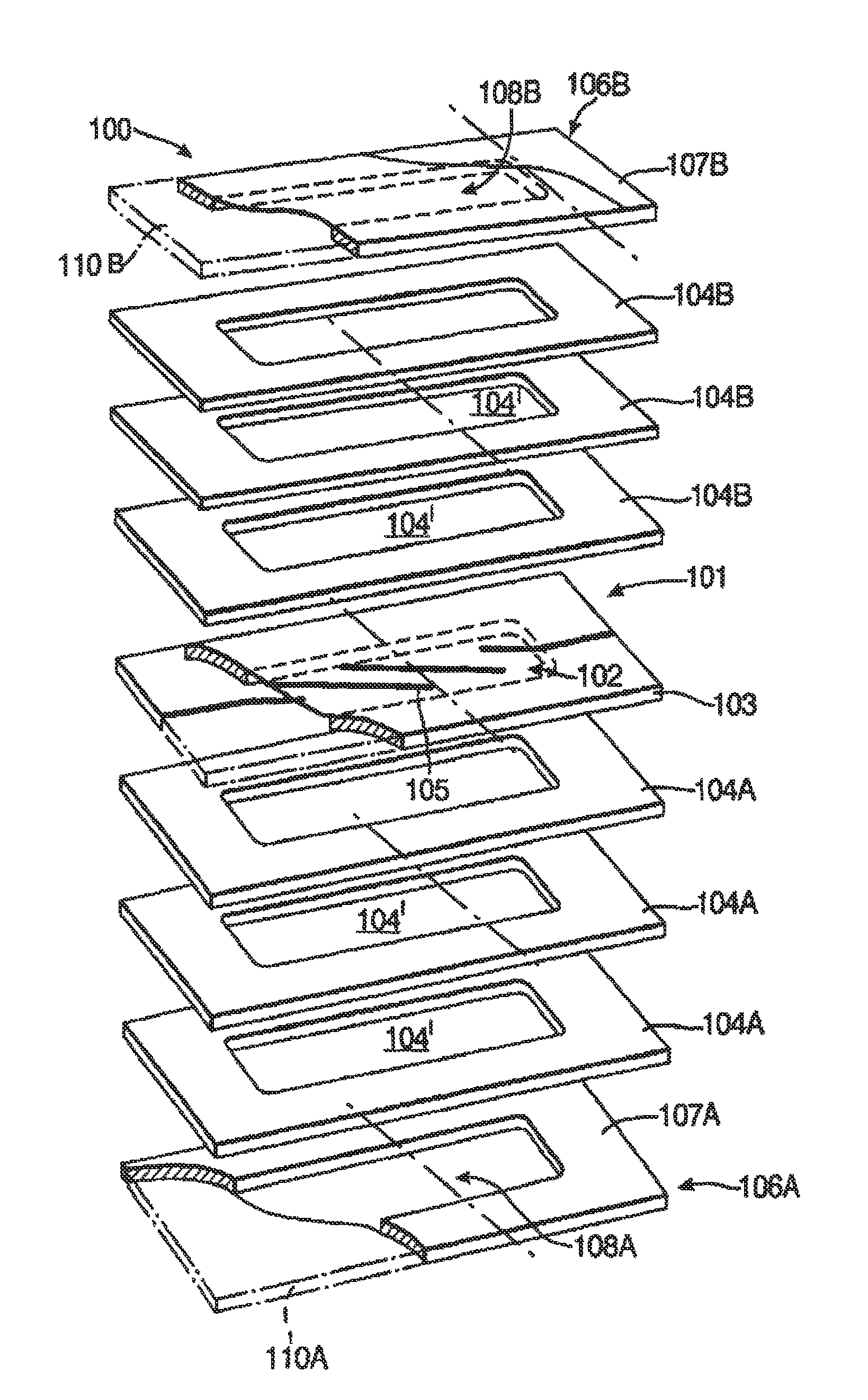
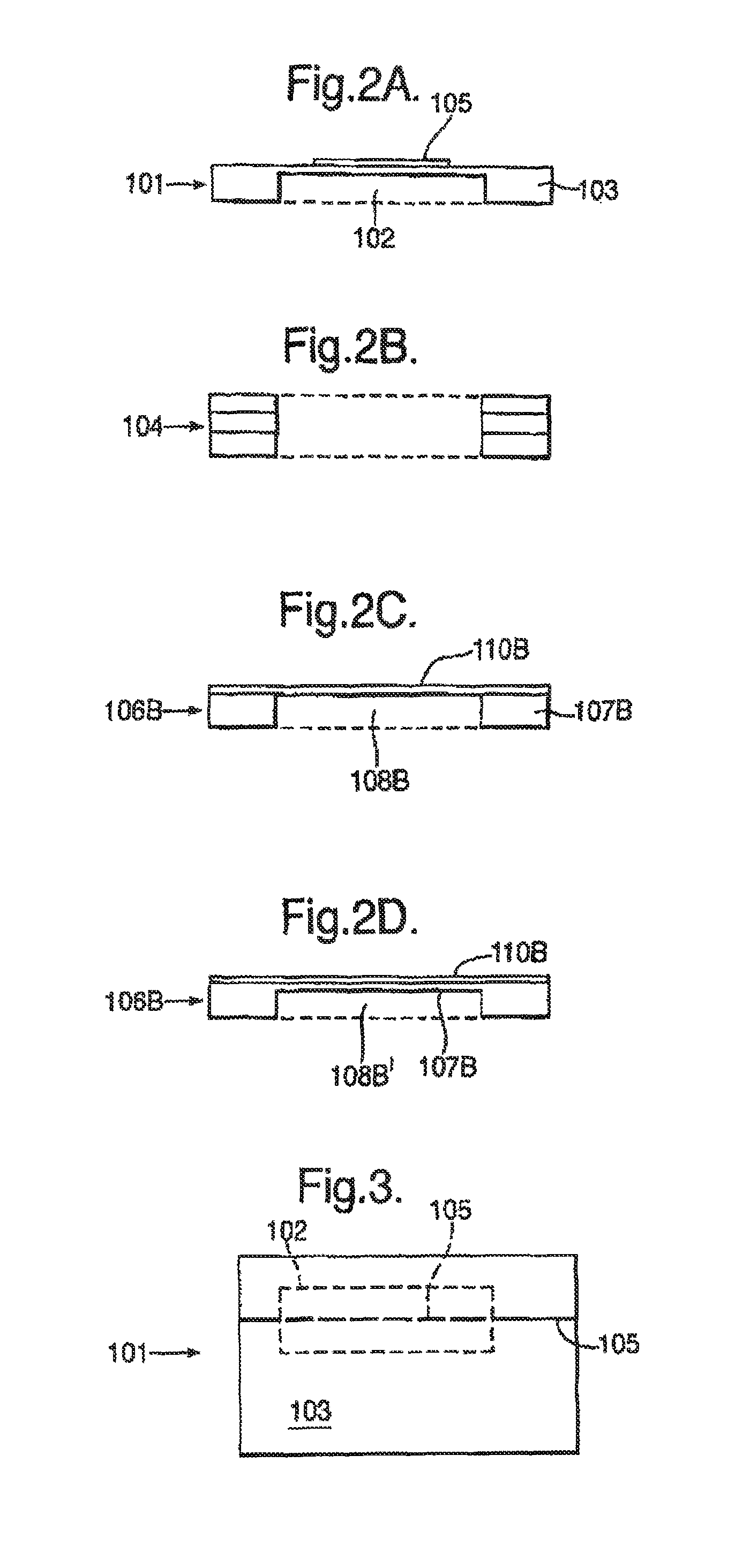
[0037]Referring to the exploded view of FIG. 1, there is shown a circuit supporting layer 101. The layer 101 includes a rectangular piece of LCP material 103 having a thickness chosen to suit the particular application. The LCP layer 103 includes a rectangular recess 102 (around 25 mm×10 mm in area in this particular example) in its lower surface. The LCP layer 103 can either be formed including such a recess, or the recess can be formed in a flat piece of material using a plasma or laser etching process, for example. The thickness of the (remaining) LCP material in the recessed area can be in the region of about 1 to 5 μm, and provides a thin membrane for supporting circuit components, as will be described below. It will be ...


PUM

PropertyMeasurementUnit
Lengthaaaaaaaaaa
Timeaaaaaaaaaa
Lengthaaaaaaaaaa

Abstract

A microwave circuit assembly includes a Liquid Crystalline Polymer (LCP) layer that supports at least one microwave circuit component. First and second ground plane layers form the outer surfaces of the assembly and these are spaced apart at least partially by a gas, a mixture of gases, or a vacuum, from the LCP supporting layer and the at least one microwave circuit.

Description

RELATED APPLICATION INFORMATION[0001]This application is a United States National Phase Patent Application of International Patent Application No. PCT / GB2008 / 050440 which was filed on Jun. 13, 2008, and claims priority to British Patent Application No. 0712523.0, filed on Jun. 28, 2007, and claims priority to European Patent Application No. 07270034.7, filed on Jun. 28, 2007, the disclosures of each of which are incorporated herein by reference.FIELD OF THE INVENTION[0002]The present invention relates to microwave circuit assemblies.BACKGROUND INFORMATION[0003]It is common practice to fabricate microwave strip line assemblies by patterning a conductor on a laminate. The pattern is capped with a second laminate in a bonded assembly. The outer surfaces of the assembly can then be clad with a conducting material to form two ground planes. Shielding vias may be used to connect the ground planes. Multi-layer circuits of this form can be produced and this type of bonded assembly is relati...

Claims


Application Information

Patent Timeline
IPC IPC(8): H01P3/08
CPCH01P1/203H01P3/08Y10T29/49117
Inventor NIMAN, MURRAY JERELGREED, ROBERT BRIAN
Owner BAE SYSTEMS PLC
Why Eureka
Try Eureka