Veterinary anesthesia monitor system

a monitor system and anesthesia technology, applied in the direction of valve operating means/release devices, process and machine control, instruments, etc., can solve the problems of not yielding the proper partial pressure of the inhalant anesthetic delivered to the patient, the anesthesia vaporizer may not be properly adjusted, and the oxygen delivered from the anesthesia machine can be contaminated with inhalation anesthetic,

Inactive Publication Date: 2011-08-16
INTELLIVET ANESTHESIA EQUIP
View PDF12 Cites 30 Cited by
  • Summary
  • Abstract
  • Description
  • Claims
  • Application Information

AI Technical Summary

Benefits of technology

[0022]Another aspect of this broad object of the invention can be to provide additional computer hardware which provides storage and retrieval of data and programmed or programmable elements relating to anesthesia profiles for various anesthetics and inhalation anesthesia applications. The programmed or programmable elements can further provide a program which allows tracking of the anesthesia profiles in conjunction with monitoring of the conditions in the re-breathing circuit to assure that the desired anesthesia profile is being correctly implemented.

Problems solved by technology

A significant problem with conventional anesthetic delivery devices and procedures can be that the anesthetic vaporizer may not be properly readjusted after delivery of anesthetic during the induction period.
Even during resuscitation attempts oxygen delivered from the anesthesia machine can be contaminated with inhalation anesthetic because the vaporizer has been accidentally been left on the full ON position.
Another significant problem with conventional anesthesia delivery devices and procedures can be that visual observation of the amount of anesthetic in the anesthetic vaporizer can be required to ensure that the proper amount of anesthetic is held for delivery by the anesthetic vaporizer to the inhalation circuit.
However, visualization to estimate the amount of anesthetic in the anesthetic vaporizer and comparison to the prior estimated amount of anesthetic in anesthetic vaporizer to determine the amount of anesthetic delivered from the anesthetic vaporizer may not yield consistent delivery of anesthetic from the anesthetic vaporizer or the proper partial pressure of the inhalant anesthetic delivered to the patient.
Inconsistent, inaccurate, or undesired delivery rates of anesthetic from the anesthetic vaporizer or partial pressures of anesthetic inhalants delivered to the patient can result from the failure of or inconsistency of the operator.
In certain instances, the operator may simply become distracted from visualizing, or forget to visualize, the amount of anesthetic in the anesthetic vaporizer.
Also, visualization by the operator may simply be in error as to the actual amount of anesthetic in the anesthetic vaporizer.
In addition, anesthetic visualization and calibration of the anesthetic vaporizer can be complicated by the numerous different anesthetics which may be delivered to patients, each of which may have unique anesthetic characteristics (density, boiling point, vaporization rate, or the like).
In other instances, conventional vaporizers may be poorly designed contributing to operator error, fail to operate, operate out of calibration, operate inconsistently, or operate in an other undesired manner, making estimation of anesthetic delivery less consistent, less precise, or in some cases not possible at all.
Another significant problem with conventional anesthesia delivery devices and methods can be that only visualization or dependence upon calibration of the anesthetic vaporizer may used to estimate the amount of anesthetic delivered from the anesthetic vaporizer to the re-breathing system.
As discussed above, reliance on calibration or visualization to estimate the partial pressure of anesthetic in the re-breathing system may not provide information as to the actual condition of the gas mixture inhaled by the patient, or the subsequent condition of the gas mixture exhaled by the patient.
The absorbent, which initially absorbs substantially all the CO2, gradually becomes saturated until the absorbent no longer retains CO2 and levels of CO2 in the re-breathing system can rise to levels harmful to the patient.
As such, color change can be unreliable and harmful CO2 levels can build up in the re-breathing circuit of conventional anesthesia device of which the operator can be unaware resulting in harm to the patient.

Method used


Image

  • Veterinary anesthesia monitor system
  • Veterinary anesthesia monitor system
  • Veterinary anesthesia monitor system

Examples


Embodiment Construction

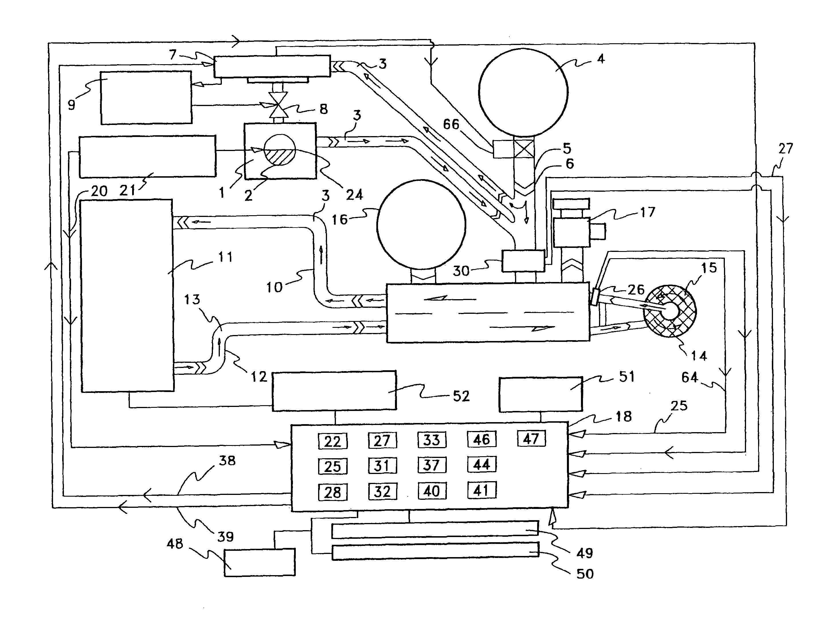
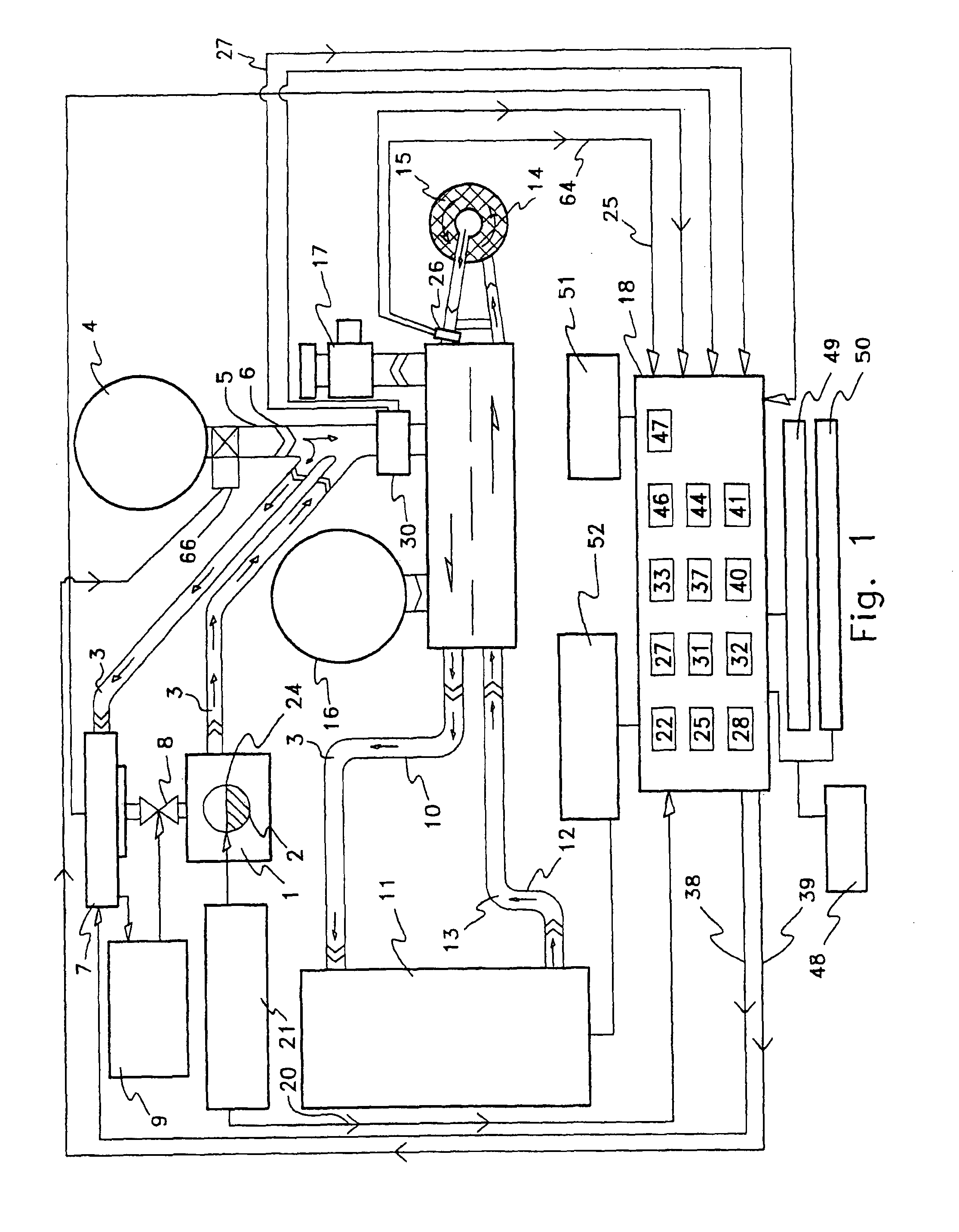
[0032]In general, an anesthesia device which monitors the amount of anesthetic held for vaporization and characteristics of the mixture of gases in the circular re-breathing system. Specifically, a veterinary anesthesia device which can monitor the amount of anesthetic held in the vaporizer and which can monitor the amount of anesthetic and amount of carbon dioxide in the circular re-breathing system.

[0033]First referring primarily to FIG. 1, an embodiment of the anesthesia device in accordance with the invention provides an anesthetic source (1) in which an amount of anesthetic (2) is established. The anesthetic source (1) entrains an amount of anesthetic (2), such as, Halothane, Enflurane, Isoflurane, Desflurane, Sevflurane, or the like, in a flow of gases (3). The flow of gases (3) can be gas flow generator (4) which without limitation can comprise a compressed gas cylinder coupled to a gas pressure regulator (5) and a gas flow meter (6). The gas flow generator can establish a fl...


PUM


Abstract

A veterinary anesthesia monitor system useful in establishing, maintaining, and reporting upon the anesthesia gas mixture delivered to or exhaled by a patient.

Description

[0001]This application claims the benefit under 35 U.S.C. §119(e) of U.S. provisional patent application No. 60 / 530,689, filed Dec. 17, 2003, hereby incorporated by reference herein.I. BACKGROUND[0002]An anesthesia device which monitors the amount of anesthetic held for vaporization and the amount of anesthetic and carbon dioxide in the mixture of gases in the circular re-breathing system.[0003]During veterinary or human surgical procedures, a conventional anesthesia device entrains an amount of anesthetic into a mixture of gases utilizing an anesthetic vaporizer. The anesthetic entrained in the mixture of gases can be delivered for inhalation by a patient in a circular re-breathing system. The depth of general anesthesia depends on the partial pressure (or gas fraction) exerted by the inhalation anesthetic (or inhalation agent) on the patient's brain. This brain partial pressure of the inhalation anesthetic depends on arterial blood partial pressure of the inhalation anesthetic whi...

Claims


Application Information

Patent Timeline
Patent Type & Authority Patents(United States)
IPC IPC(8): A61M15/00F16K31/02A61M16/00
CPCA61D7/04A61M16/01A61M16/104A61M16/209A61M16/0078A61M16/18A61M16/22A61M2016/103A61M2016/1035A61M2205/3306A61M2205/3317A61M2205/3368A61M2205/3379A61M2205/3382A61M2205/3386A61M2205/502A61M2230/432A61M2250/00
Inventor LEONARD, ROBERT DEANWILSON, DAVID ROBERT
Owner INTELLIVET ANESTHESIA EQUIP
Why Eureka
Try Eureka