
Integrated circuit and device for mobile communications

a mobile communication and integrated circuit technology, applied in multiplex communication, transmission monitoring, receiver monitoring, etc., can solve the problem of extreme deterioration of the s/n ratio of the rf test signal

Inactive Publication Date: 2011-08-09
RENESAS ELECTRONICS CORP
View PDF13 Cites 30 Cited by
  • Summary
  • Abstract
  • Description
  • Claims
  • Application Information

AI Technical Summary

Benefits of technology

The patent text describes a problem in wireless communication devices where the mismatch of the received signal needs to be calibrated. However, generating a test signal for calibration from the transmission voltage controlled oscillator (Tx-VCO) can be difficult due to the large power consumption of the Tx-VCO and the possibility of injection lock. The inventors have developed a solution to this problem by using the voltage-controlled oscillator for receiver (Rx-VCO) to generate the test signal for calibration, but the severity of the test conditions in the highest frequency band is the greatest. The patent text describes the technical effects of the invention and the solution to this problem.

Problems solved by technology

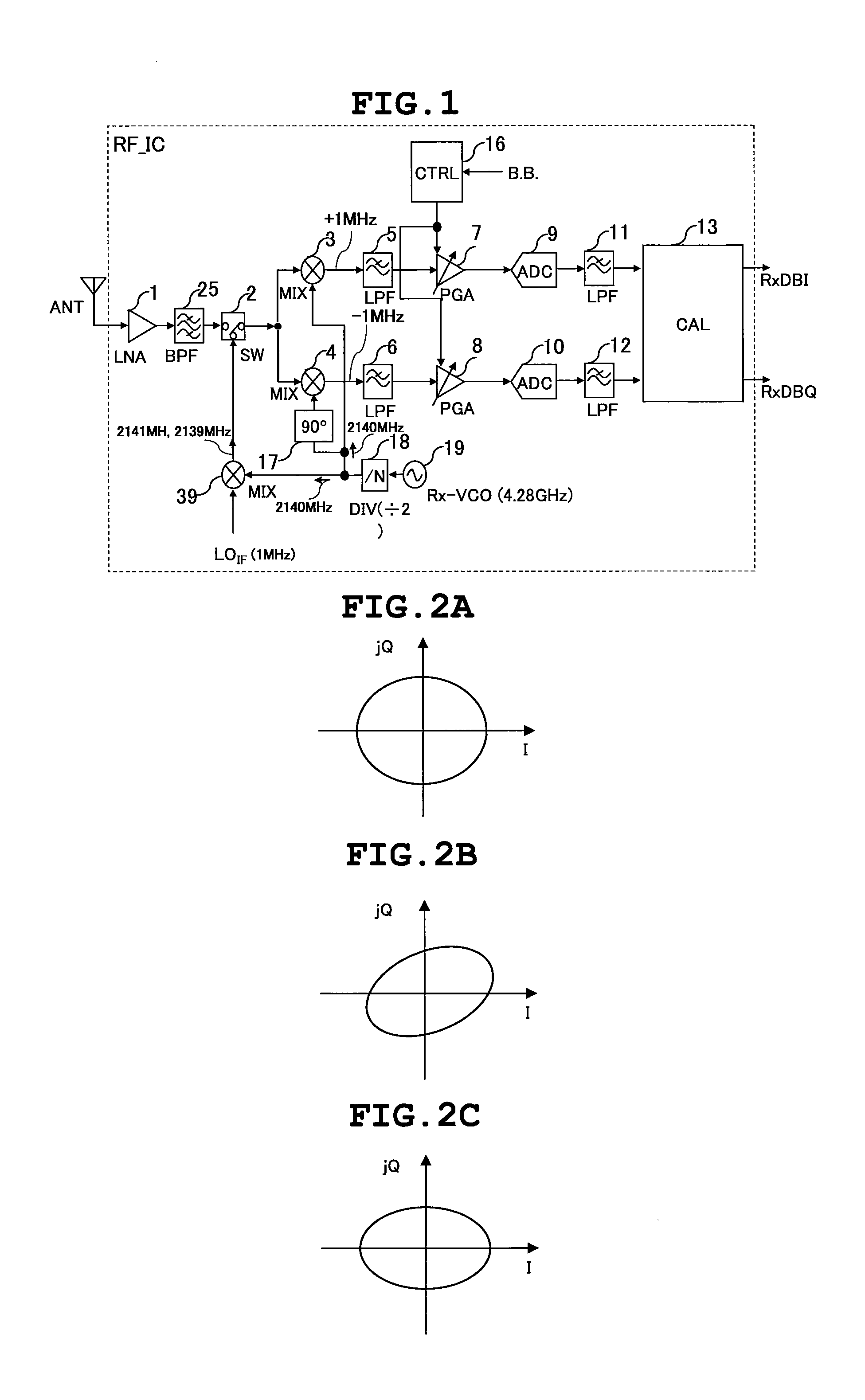
However, as described in the patent document 2, the study of the inventors clarifies that generating of the RF test signal for mismatch calibration for receiver from the transmission voltage controlled oscillator (Tx-VCO) involves the following problems.
Further, in the case where the oscillation frequency of the Tx VCO is extremely closer to that of the Rx-VCO in a direct conversion transmission / reception device, there is a possibility that two voltage controlled oscillators cause injection lock, and thus the S / N ratio of the RF test signal is extremely deteriorated.

Method used


Image

  • Integrated circuit and device for mobile communications
  • Integrated circuit and device for mobile communications
  • Integrated circuit and device for mobile communications

Examples


Embodiment Construction

IC according to still another embodiment of the present invention;

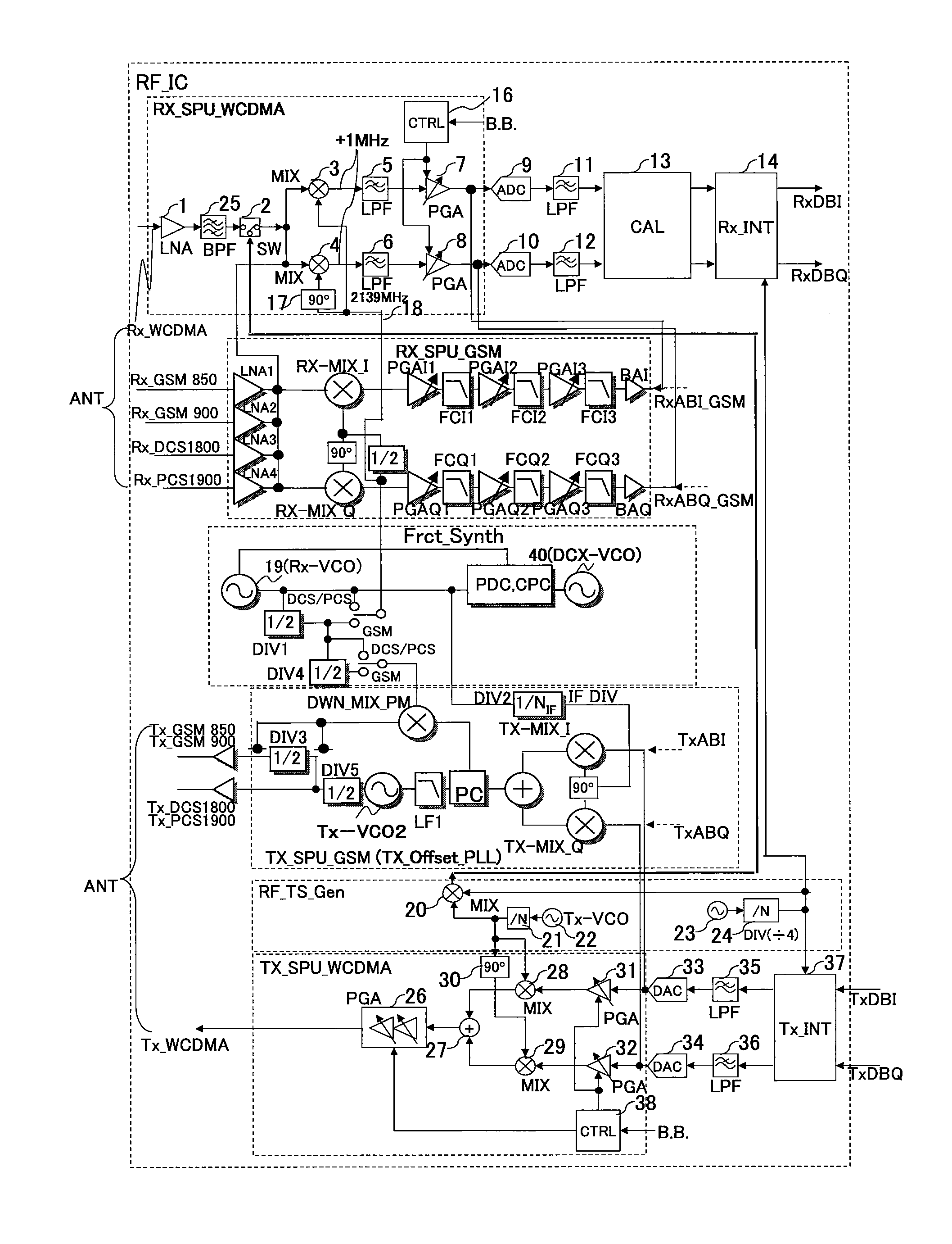
[0041]FIG. 9 is a block diagram showing a configuration of a mobile phone in which the RF IC according to the various embodiments of the present invention, an RF module incorporating an antenna switch MMIC and an RF power amplifier, and a baseband signal processing LSI are mounted;

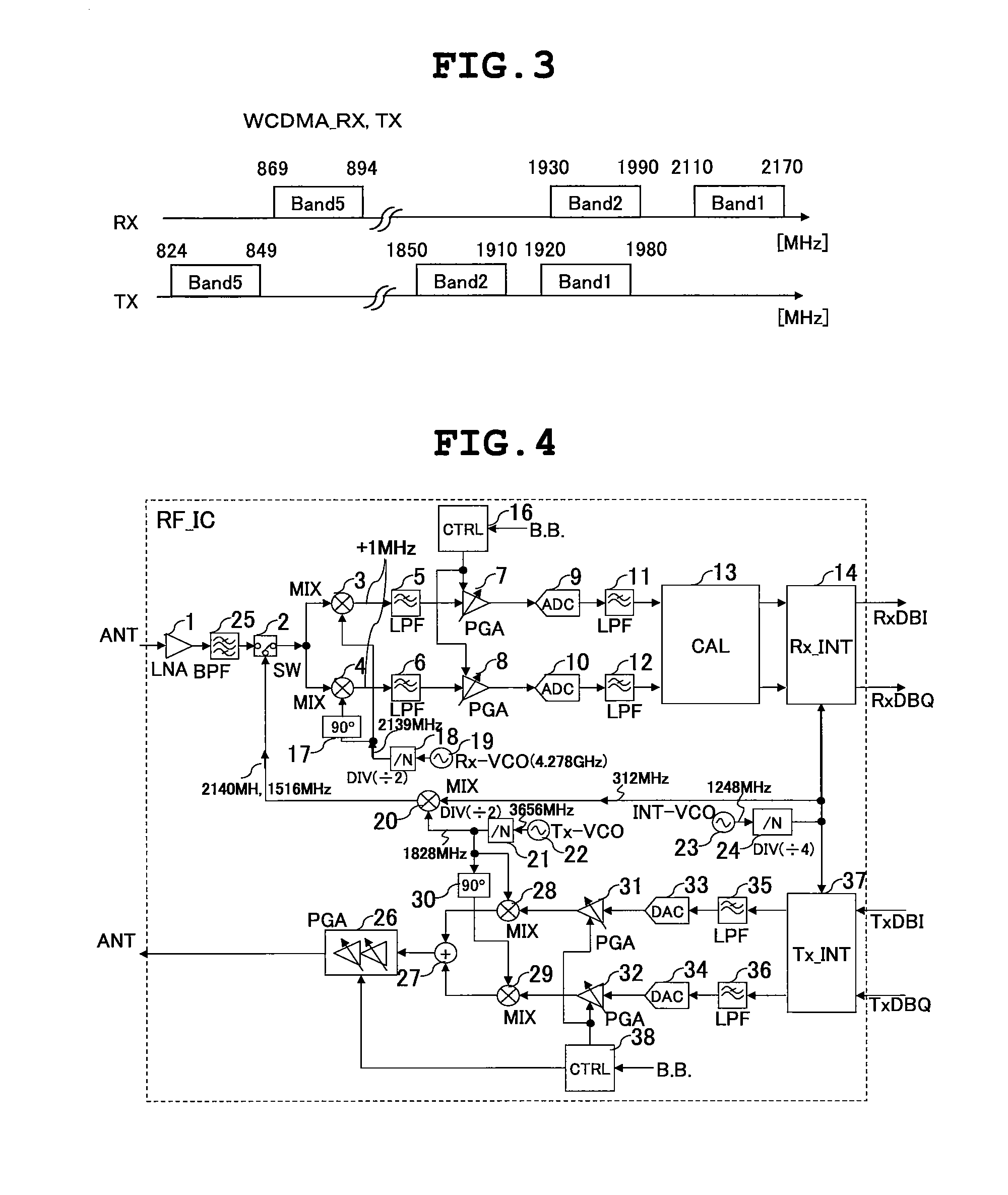
[0042]FIG. 10 is a diagram showing the transmission / receiving bands of various communication systems;

[0043]FIG. 11 is a block diagram showing an example of an other-system transmission circuit TX_SPU_GSM shown in FIG. 8;

[0044]FIG. 12 is a block diagram showing another example of the other-system transmission circuit TX_SPU_GSM shown in FIG. 8;

[0045]FIG. 13 is a block diagram showing an example of a mismatch calibration for receiver circuit 13 of the RF IC shown in FIG. 4; and

[0046]FIG. 14 is a block diagram showing another example of the mismatch calibration for receiver circuit 13 of the RF IC shown in FIG. 4.

DETAILED DESCRIPTION OF THE PRE...


PUM


Abstract

When generating an RF test signal for mismatch calibration for receiver in order to calibrate reception mismatch of an I-phase signal and a Q-phase signal that are output from demodulated signal processing circuits coupled to mixers for receiving, a Tx VCO avoids covering the higher frequency of an RF received signal in an FDD system. An RF test signal generating unit generates, in a calibration mode of a mismatch calibration for receiver circuit, the RF test signal by using an oscillation output signal of the Tx VCO and other circuits, and supplies the same to the mixers for receiving via a switch. The RF test signal has a frequency within an RF reception frequency band that is higher than that of an RF transmission signal with the maximum frequency band of multiband radio frequency communications. By switching the switch in a reception mode, an output of a low-noise amplifier that amplifies the RF received signal received by an antenna is supplied to each of the mixers for receiving.

Description

CLAIM OF PRIORITY[0001]The present application claims priority from Japanese application JP 2006-308821 filed on Nov. 15, 2006, the content of which is hereby incorporated by reference into this application.FIELD OF THE INVENTION[0002]The present invention relates to a radio frequency integrated circuit and a wireless communication terminal device using the same, and particularly to a useful technique for generating a test signal for calibrating mismatch of a received signal, such as mismatch of the amplitudes and phases of an in-phase component signal I and a quadrature component signal Q in an orthogonal demodulated signal.BACKGROUND OF THE INVENTION[0003]Ubiquitous coverage which is the capability of a communication terminal device such as a mobile phone terminal that allows for wireless communications anywhere in the world is not practically used now, but is currently being developed.[0004]These mobile systems include cellulars of GSM, GPRS, EDGE, WCDMA, DCS, and PCS. In the cha...

Claims


Application Information

Patent Timeline
Patent Type & Authority Patents(United States)
IPC IPC(8): H04W24/00H04B17/00H04B1/3822H04B1/40H04B1/707H04B17/29H04J13/00H04L27/227H04L27/38
CPCH04B1/30
Inventor MAEDA, KOJITANAKA, SATOSHIYAMAWAKI, TAIZOAKAMINE, YUKINORIITO, MASAHIRO
Owner RENESAS ELECTRONICS CORP
Learn More