Optical disk device and control method for the same

a control method and optical disk technology, applied in the direction of digital signal error detection/correction, instruments, recording signal processing, etc., can solve the problems of inability to correct the reading of data recorded on the optical disk, the optical power variation, and the mark edge recording, etc., to achieve high reliability and high-quality reproduction of the signal

Inactive Publication Date: 2011-08-09
HITACHI CONSUMER ELECTRONICS CORP +1
View PDF12 Cites 0 Cited by
  • Summary
  • Abstract
  • Description
  • Claims
  • Application Information

AI Technical Summary

Benefits of technology

[0016]According to the invention, an optical disk device capable of recording and / or reproducing information on optical disks with high reliability by setting an optimum focus position that produces a high-quality reproduction signal; and a control method for the optical disk device can be obtained.

Problems solved by technology

However, as discussed in JP08-115521 A, mark edge recording has a drawback in that a recording mark, which is supposed to have a specified length when recorded, may have a different length, depending on the optical power during data recording.
When the recording mark has a length different from its proper length, the positions of the edges of the recording mark are shifted, which inhibits correct reading of data recorded on the optical disk.
There are various probable causes of variations in optical power during recording, one of which is defocus during data recording.
In practice, defocus reduces the optical power density during data recording and causes a shortage of power, thereby inhibiting formation of a recording mark of the specified length.
Defocus also lowers the resolution during data recording as well as data reproduction and may cause data read errors.

Method used


Image

  • Optical disk device and control method for the same
  • Optical disk device and control method for the same
  • Optical disk device and control method for the same

Examples


embodiment 1

(1) Embodiment 1

(1-1) Configuration of Optical Disk Device According to Embodiment 1

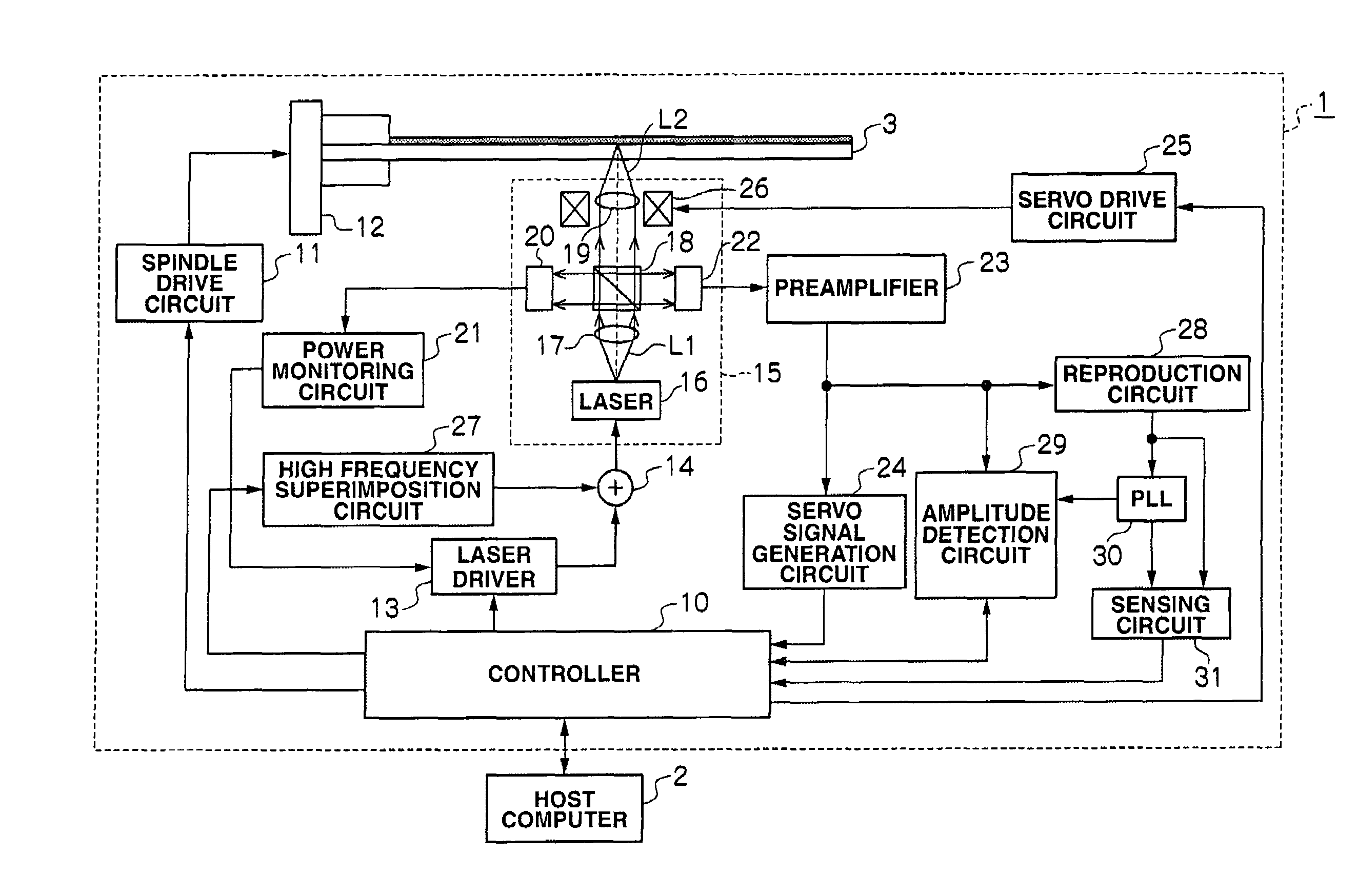
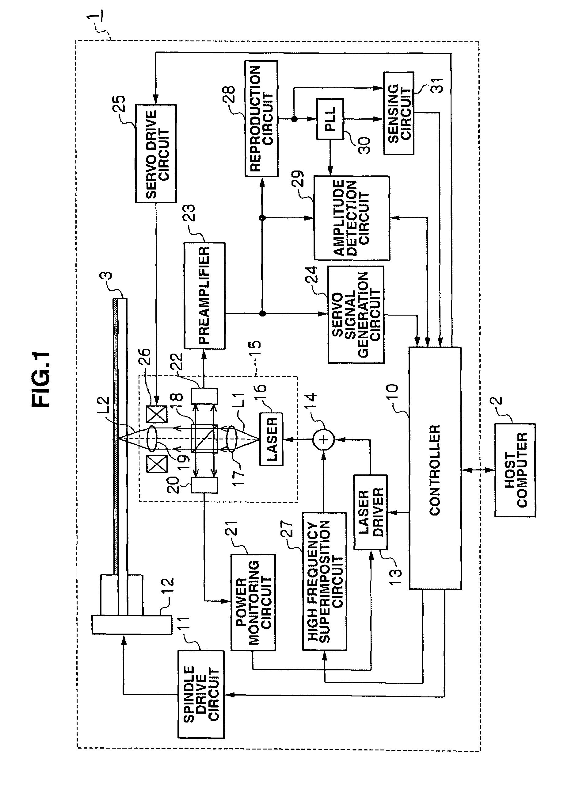
[0032]In FIG. 1, reference numeral 1 indicates an optical disk device according to Embodiment 1. This optical disk device 1 is configured so that it can record / reproduce data on an optical disk 3 such as a DVD in response to a request from a host computer 2.

[0033]In the optical disk device 1, various commands from the host computer 2 are sent to a controller 10. The controller 10 is composed of a microcomputer including a CPU (Central Processing Unit) and an internal memory storing various control programs, and executes necessary controls and calculations in response to commands from the host computer 2 or based on various information provided from various circuits inside the optical disk device 1.

[0034]The procedure performed when the controller 10 receives a record command from the host computer 2 will be described below. When the controller 10 receives a record command from the host computer 2, it...

embodiment 2

(2) Embodiment 2

(2-1) Principle

[0072]The optimum focus position learning in Embodiment 1 is performed where the reproduction circuit system has no AGC (Auto Gain Controller) circuit that maintains the amplitude of the RF signal constant.

[0073]Where the reproduction circuit system does not include an AGC circuit, the level of the RF signal is likely to change due to noise and so it is hard to obtain good reproduction data. Accordingly, in order to obtain a good quality reproduction signal, it is preferable that the reproduction circuit system has an AGC circuit.

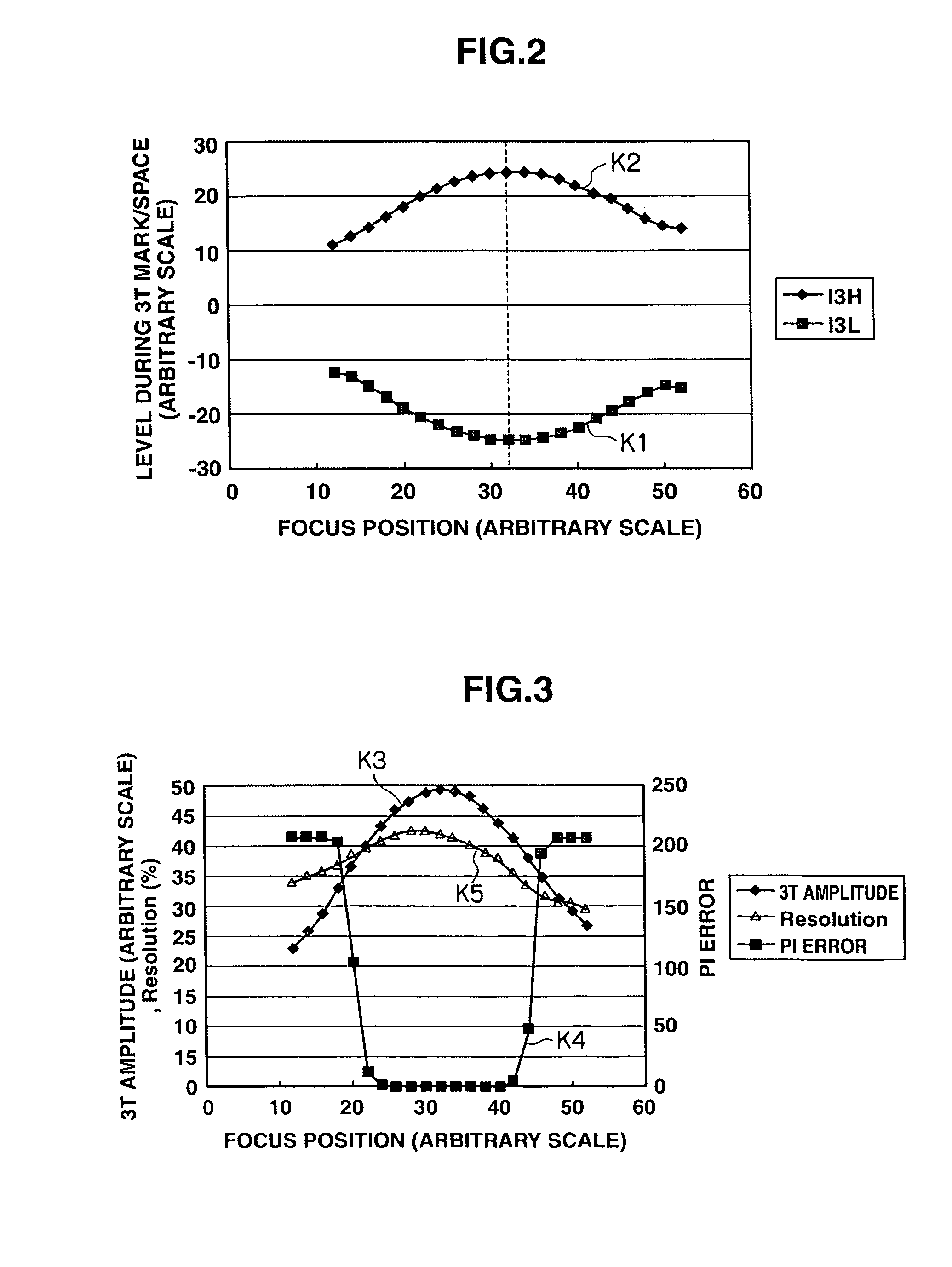
[0074]However, when an AGC circuit is provided in the reproduction circuit, AGC processing performed by the AGC circuit reduces the variations due to defocus in the amplitude of the RF signal. Therefore, when reproducing the minimum-length recording marks repeatedly formed on the optical disk 3 by changing the focus position in the same manner as in FIG. 2, neither the level of the RF signal during the period corresponding to ...


PUM

PropertyMeasurementUnit
lengthaaaaaaaaaa
lengthaaaaaaaaaa
lengthaaaaaaaaaa

Abstract

Provided is an optical disk device capable of recording and / or reproducing information on optical disks with high reliability; and a method for controlling the optical disk device. The position of an optical lens where the amplitude of a reproduction signal during the period corresponding to a minimum-length recording mark and a space having the same length reaches its maximum is detected; and the detected position is set as a reference position for the objective lens relative to the optical disk, for use in focus control. Also, the position of the objective lens where the result of multiplication of resolution and modulation becomes greatest is detected; and the detected position is set as a reference position for the objective lens relative to the optical disk, for use in focus control.

Description

CROSS-REFERENCES TO RELATED APPLICATIONS[0001]This application relates to and claims priority from Japanese Patent Application No. 2007-191325, filed on Jul. 23, 2007, the entire disclosure of which is incorporated herein by reference.BACKGROUND[0002]1. Field of the Invention[0003]The invention relates generally to an optical disk device and a control method for the optical disk device, and is suitable for use in, for example, an optical disk device compatible with DVDs (Digital Versatile Discs).[0004]2. Description of Related Art[0005]Mark edge recording—a method of recording information on the edges of a recording mark—has been used as one of the methods for recording data on optical disks. This mark edge recording has an advantage over mark position recording—a method of recording information in the center of the recording mark—in high density recording.[0006]However, as discussed in JP08-115521 A, mark edge recording has a drawback in that a recording mark, which is supposed to ...

Claims


Application Information

Patent Timeline
Patent Type & Authority Patents(United States)
IPC IPC(8): G11B7/00
CPCG11B7/0945G11B7/0908
Inventor TODA, TSUYOSHIISHII, TOSHIKI
Owner HITACHI CONSUMER ELECTRONICS CORP
Why Eureka
Try Eureka