
Electromagnetic directional measurements for non-parallel bed formations

a non-parallel bed and directional measurement technology, applied in seismology for waterlogging, detection using electromagnetic waves, instruments, etc., can solve the problems of poor well placement, time-consuming, and inability to achieve real-time interpretation or mwd

Active Publication Date: 2011-08-02
SCHLUMBERGER TECH CORP
View PDF15 Cites 17 Cited by
  • Summary
  • Abstract
  • Description
  • Claims
  • Application Information

AI Technical Summary

Benefits of technology

The patent text describes a method for determining the direction of a more conductive layer in a logging tool in a deep imaging induction tool. The method uses an orientation vector that is directed towards the more conductive layer and away from the most resistive layer. The method uses a geosteering vector to determine the direction of the more conductive layer in a non-planar formation. The method can be used in real-time processing and does not require two or three dimensional modeling calculations. The technical effect of the patent text is to provide a more efficient and accurate method for drilling in non-planar formations using a logging tool.

Problems solved by technology

Often, this assumption leads to inadequate results.
However, the propagation resistivity MWD tools are non-azimuthal, and therefore do not indicate whether formation boundaries are above or below the tool.
As a result of these deficiencies, the use of propagation resistivity MWD tools can lead to poor well placement.
However, this definition conveys no information as whether the tool string is approaching the reservoir boundary from above or below the boundary.
Because non-planar formation geometry is often encountered, two-dimensional and three-dimensional modeling is required, which is time-consuming and not suitable for real time interpretation or MWD.

Method used


Image

  • Electromagnetic directional measurements for non-parallel bed formations
  • Electromagnetic directional measurements for non-parallel bed formations
  • Electromagnetic directional measurements for non-parallel bed formations

Examples


Embodiment Construction

[0040]FIG. 1 illustrates a wellsite system in which the disclosed methods can be employed. The wellsite can be onshore or offshore. In this exemplary system, a borehole 11 is formed in subsurface formations by rotary drilling in a manner that is well known. Directional drilling can also be used, as will be described hereinafter.

[0041]A drill string 12 is suspended within the borehole 11 and has a bottom hole assembly (BHA) 100 which includes a drill bit 105 at its lower end. The surface system includes platform and derrick assembly 10 positioned over the borehole 11 and the assembly 10 includes a rotary table 16, kelly 17, hook 18 and rotary swivel 19. The drill string 12 is rotated by the rotary table 16, energized by means not shown, which engages the kelly 17 at the upper end of the drill string. The drill string 12 is suspended from a hook 18, attached to a traveling block (also not shown), through the kelly 17 and a rotary swivel 19 which permits rotation of the drill string 12...


PUM


Abstract

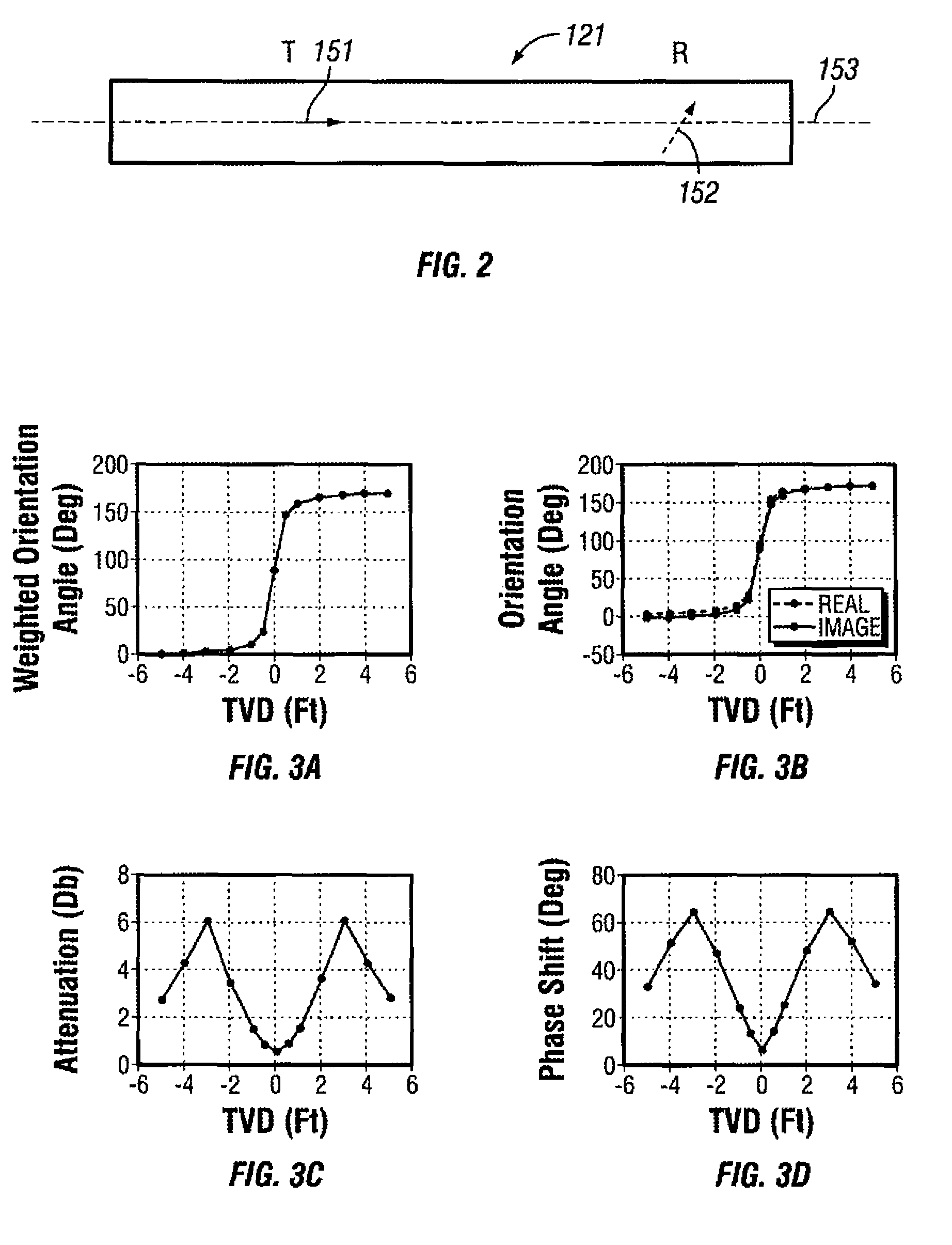
An orientation vector, referred to hereinafter as the “geosteering vector,” is directed to the more conductive formation area within the DOI of the tool and away from the more resistive formation areas. Accordingly, drilling in a direction opposite the geosteering vector leads to more resistive formation. Also, the disclosed geosteering vectors obtained from the real and imaginary components will not align with each other for non-planar formations and therefore the misalignment of the geosteering obtained from real and imaginary components is indicative of a non-planar formation. A superposition method is disclosed which can be used to calculate electromagnetic (EM) couplings in a non-planar geometry formation (as well as in a planar geometry formation) in real time, without requiring two or three dimensional modeling calculations.

Description

BACKGROUND[0001]1. Technical Field[0002]Techniques are disclosed enhancing well placement using ultra deep resistivity tools in logging while drilling (LWD), measurement-while-drilling (MWD), and directional drilling (Geo-steering) applications. The disclosed techniques include methods for locating the most conductive formation region relative to the tool, determining distances and relative directions of formation layer boundaries, whether a tool is approaching a layer boundary from above or below the layer boundary, whether a formation is planar or non-planar, and superposition techniques for evaluating complex non-planar formations in real time without carrying out multi-dimensional modeling calculations.[0003]2. Description of the Related Art[0004]An alternative to wireline logging techniques is the collection of data on downhole conditions during the drilling process. By collecting and processing such information during the drilling process, the driller can modify or correct key...

Claims


Application Information

Patent Timeline
Patent Type & Authority Patents(United States)
IPC IPC(8): G01V3/30
CPCG01V3/30
Inventor YANG, JIANLI, QIMINGOMERAGIC, DZEVATSEYDOUX, JEANTABANOU, JACQUES R.TABANOU, LEGAL REPRESENTATIVE, BERNADETTE
Owner SCHLUMBERGER TECH CORP
Learn More