Vessel, coating, inspection and processing apparatus
a technology for processing equipment and vessels, applied in packaging, plasma technique, other medical devices, etc., can solve the problems of phlebotomists using tubes that fail to draw enough blood, and achieve the effect of enhancing chemical vapor deposition
- Summary
- Abstract
- Description
- Claims
- Application Information
AI Technical Summary
Benefits of technology
Problems solved by technology
Method used
Image
Examples
working examples
Example 0
Basic Protocols for Forming and Coating Tubes and Syringe Barrels
[0676]The vessels tested in the subsequent working examples were formed and coated according to the following exemplary protocols, except as otherwise indicated in individual examples. Particular parameter values given in the following basic protocols, e.g. the electric power and process gas flow, are typical values. Whenever parameter values were changed in comparison to these typical values, this will be indicated in the subsequent working examples. The same applies to the type and composition of the process gas.
Protocol for Forming COC Tube (Used, e.g., in Examples 1, 19)
[0677]Cyclic olefin copolymer (COC) tubes of the shape and size commonly used as evacuated blood collection tubes (“COC tubes”) were injection molded from Topas® 8007-04 cyclic olefin copolymer (COC) resin, available from Hoechst AG, Frankfurt am Main, Germany, having these dimensions: 75 mm length, 13 mm outer diameter, and 0.85 mm wall th...
example 1
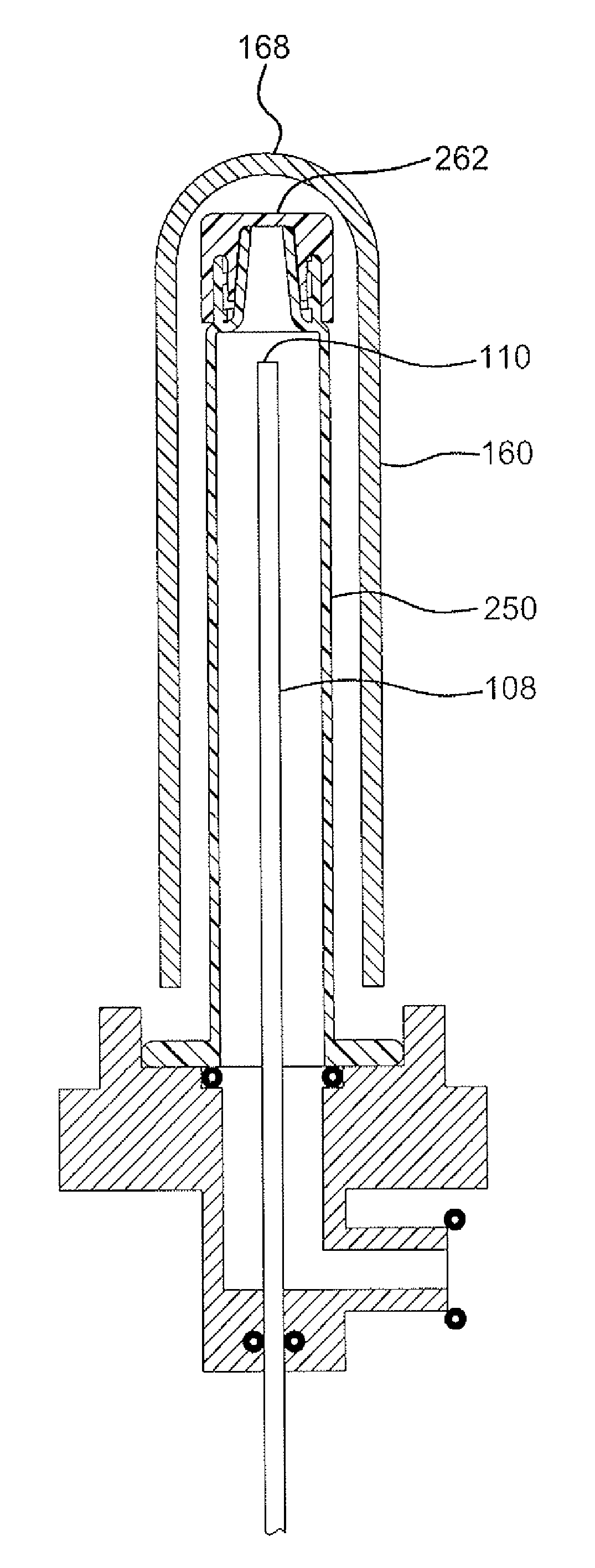
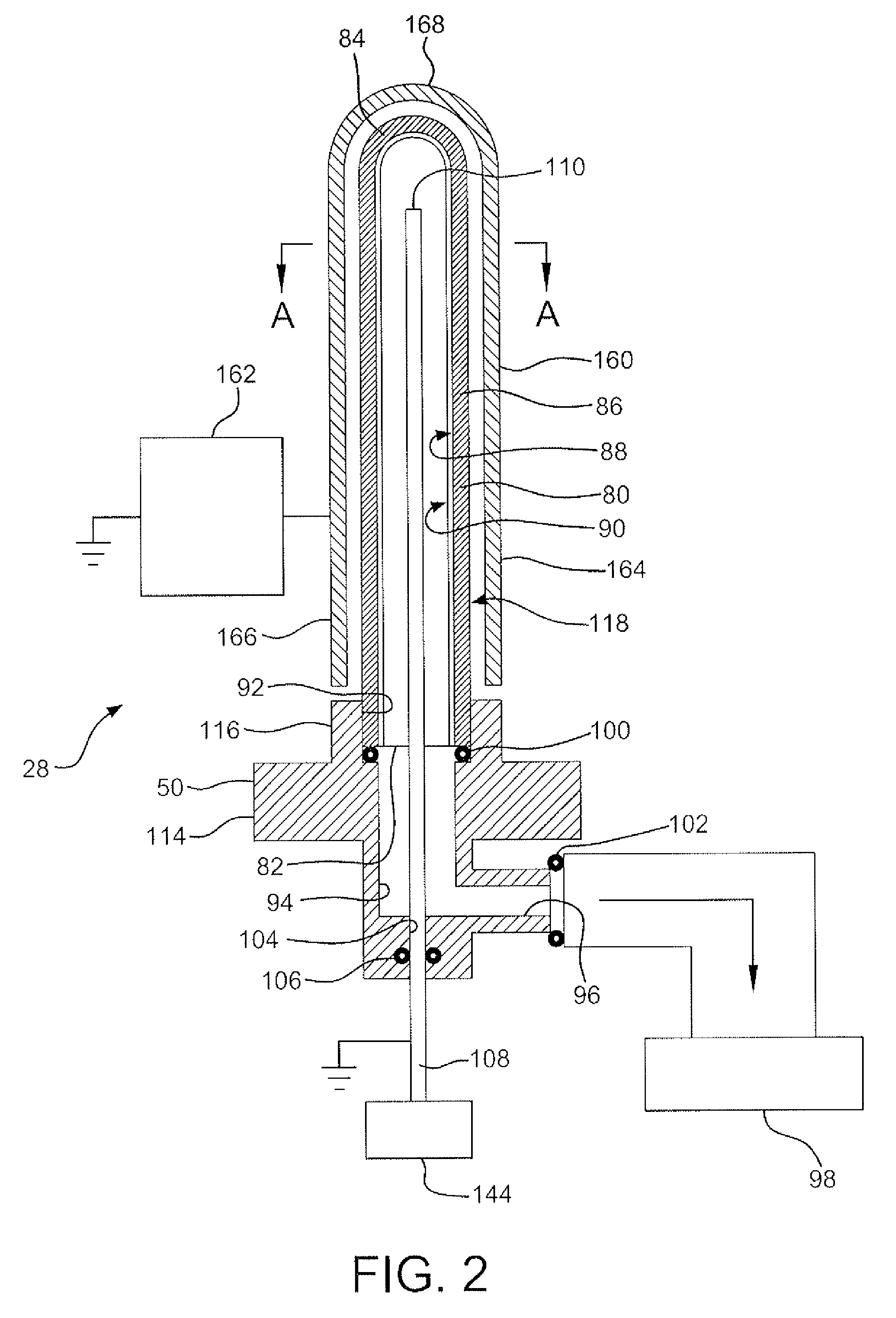
[0730]V. In the following test, hexamethyldisiloxane (HMDSO) was used as the organosilicon (“O—Si”) feed to PECVD apparatus of FIG. 2 to apply an SiOx coating on the internal surface of a cyclic olefin copolymer (COC) tube as described in the Protocol for Forming COC Tube. The deposition conditions are summarized in the Protocol for Coating Tube Interior with SiOx and Table 1. The control was the same type of tube to which no barrier coating was applied. The coated and uncoated tubes were then tested for their oxygen transmission rate (OTR) and their water vapor transmission rate (WVTR).
[0731]V. Referring to Table 1, the uncoated COC tube had an OTR of 0.215 cc / tube / day. Tubes A and B subjected to PECVD for 14 seconds had an average OTR of 0.0235 cc / tube / day. These results show that the SiOx coating provided an oxygen transmission BIF over the uncoated tube of 9.1. In other words, the SiOx barrier coating reduced the oxygen transmission through the tube to less than one ninth its va...
example 2
[0734]V. A series of PET tubes, made according to the Protocol for Forming PET Tube, were coated with SiOx according to the Protocol for Coating Tube Interior with SiOx under the conditions reported in Table 2. Controls were made according to the Protocol for Forming PET Tube, but left uncoated. OTR and WVTR samples of the tubes were prepared by epoxy-sealing the open end of each tube to an aluminum adaptor.
[0735]V. In a separate test, using the same type of coated PET tubes, mechanical scratches of various lengths were induced with a steel needle through the interior coating, and the OTR BIF was tested. Controls were either left uncoated or were the same type of coated tube without an induced scratch. The OTR BIF, while diminished, was still improved over uncoated tubes (Table 2A).
[0736]V. Tubes were tested for OTR as follows. Each sample / adaptor assembly was fitted onto a MOCON® Oxtran 2 / 21 Oxygen Permeability Instrument. Samples were allowed to equilibrate to transmission rate st...
PUM
| Property | Measurement | Unit |
|---|---|---|
| thickness | aaaaa | aaaaa |
| thickness | aaaaa | aaaaa |
| thickness | aaaaa | aaaaa |
Abstract
Description
Claims
Application Information
 - R&D
- Intellectual Property
- Life Sciences
- Materials
- Tech Scout
- Unparalleled Data Quality
- Higher Quality Content
- 60% Fewer Hallucinations
Browse by: Latest US Patents, China's latest patents, Technical Efficacy Thesaurus, Application Domain, Technology Topic, Popular Technical Reports.
© 2025 PatSnap. All rights reserved.Legal|Privacy policy|Modern Slavery Act Transparency Statement|Sitemap|About US| Contact US: help@patsnap.com


