
Ultrasonic device with longitudinal and torsional sonotrodes

a sonotrode and ultrasonic technology, applied in welding apparatus, packaging, lamination, etc., can solve the problem that the sonotrode of this device has not been particularly durable, and achieve the effect of high power

Inactive Publication Date: 2011-07-26
TELSONIC HLDG
View PDF17 Cites 3 Cited by
  • Summary
  • Abstract
  • Description
  • Claims
  • Application Information

AI Technical Summary

Benefits of technology

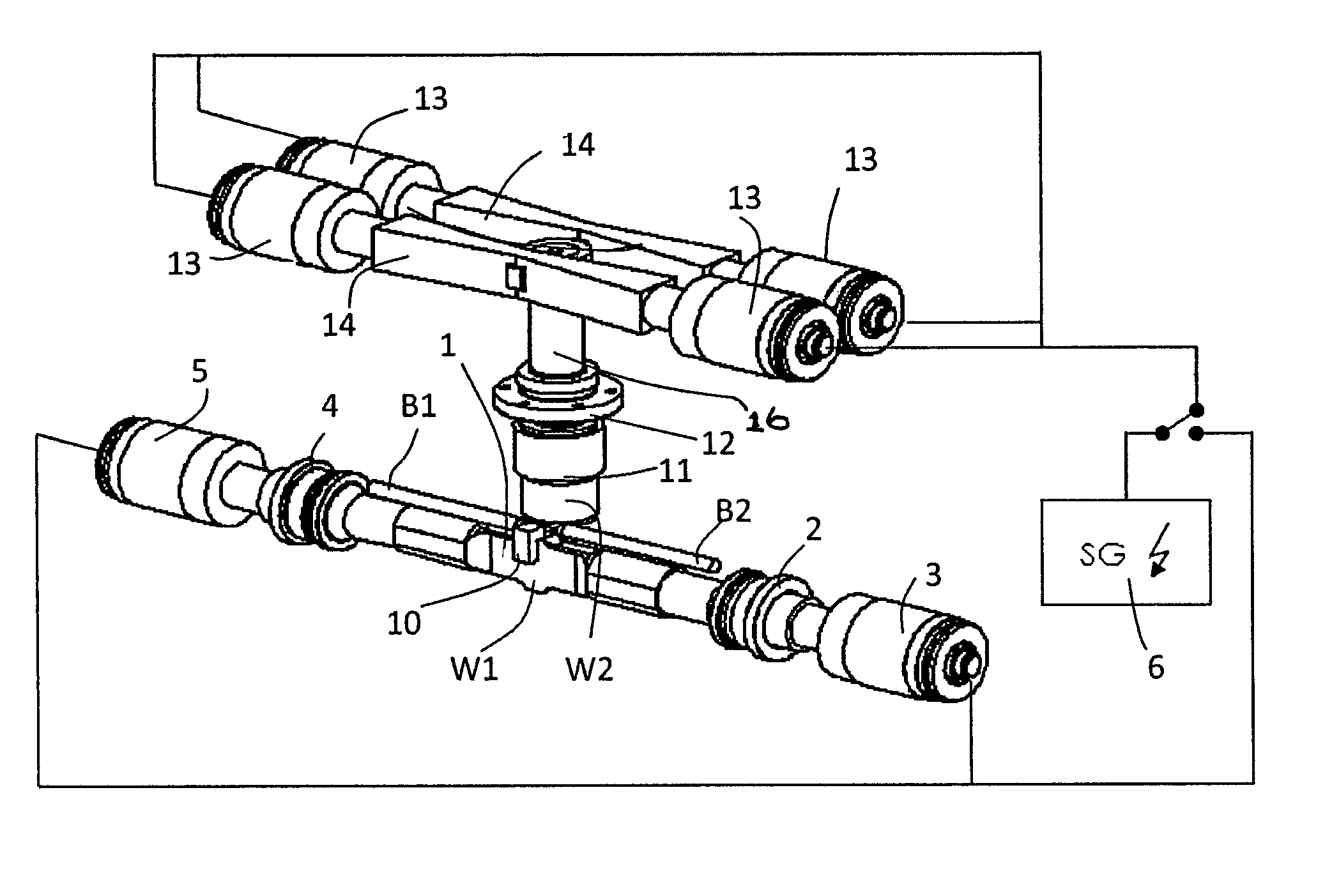
[0006]According to the provisions of the invention, it is provided that a second sonotrode which is coupled to at least one third converter and which is configured as a torsion sonotrode has a second welding surface arranged opposite the first welding surface, and wherein the first and the second sonotrodes are relatively moveable against each other so that a welding force can be applied between the first and the second welding surface to the components to be connected. —The power transferred to the components to be welded can be significantly increased with the suggested ultrasonic welding device. In particular, with this, thick-walled components can also be connected by ultrasonic welding. A further advantage of the suggested ultrasonic welding device is that the torsion sonotrode can only be moved with a vertical movement, i.e. without horizontally directed movements, against the first sonotrode for welding the components. Such a movement can be performed easily and quickly. A vertical movement unit required for this is easy and inexpensive to provide. This can increase the production speed for components to be connected with each other.
[0009]In an advantageous arrangement, the first welding surface is provided on an anvil-like projection provided in the middle of the first sonotrode. The first sonotrode is advantageously designed symmetrically, i.e., in reference to a horizontal symmetry plane, a further anvil-like projection is provided on the first sonotrode opposite the anvil-like projection. With the suggested embodiment of the first sonotrode, a particularly great amount of power output on the components to be welded together can be achieved.
[0011]According to an advantageous embodiment, the second sonotrode is coupled via a third booster to the at least one third converter. The provision of the third booster makes it possible to adjust the amplitude of the second sonotrode.

Problems solved by technology

The sonotrode of this device has not proven to be especially durable 1.

Method used


Image

  • Ultrasonic device with longitudinal and torsional sonotrodes
  • Ultrasonic device with longitudinal and torsional sonotrodes
  • Ultrasonic device with longitudinal and torsional sonotrodes

Examples


Embodiment Construction

[0024]The figures show an ultrasonic welding device for welding of two metallic components B1, B2, for example, two braids having a diameter of more than 8 mm. A rod-shaped first sonotrode 1 is connected on its first end E1 via interposition of a first booster 2 to a first converter 3. A second end E2 of the first sonotrode 1 is connected to a second converter 5 via interposition of a second booster 4. The arrangement is symmetrical with regard to a median plane. The median plane corresponds to intersecting line A-A in FIG. 2. The first converter 3 and the second converter 5 can be operated together with a first generator 6. Due to this, the longitudinal waves W1 are impressed on the first sonotrode 1.

[0025]As is particularly shown in FIGS. 2 and 3, the first sonotrode 1 has an anvil-like projection 7 in its middle and a symmetrical counter projection 8 located opposite. The projection 7 is provided with an even welding surface 9 on which the metallic components B1, B2 to be welded ...


PUM

PropertyMeasurementUnit
diameteraaaaaaaaaa
frequencyaaaaaaaaaa
frequencyaaaaaaaaaa

Abstract

An ultrasonic welding device for welding two components has a rod-shaped first sonotrode for the generation of longitudinal waves and is coupled on its first end to a first converter and on its second end opposite the first end to a second converter. A first welding surface is provided in the middle of the first sonotrode. To improve durability and welding performance, a second sonotrode which is coupled to at least one third converter and is configured as a torsion sonotrode, has a second welding surface arranged opposite the first welding surface. The first and second sonotrodes can be moved relatively to each other such that a clamping force between the first and the second welding surface can be applied to the components to be connected.

Description

RELATED APPLICATIONS[0001]The present application claims the priority of German Application No. 10 2009 027 021.3 filed Jun. 18, 2009, the disclosure of which is hereby incorporated by reference herein in its entirety.BACKGROUND OF THE INVENTION AND RELATED ART STATEMENT[0002]The invention relates to an ultrasonic welding device.[0003]The invention generally relates to the field of ultrasonic welding. In particular, it relates to the field of ultrasonic welding of metallic components. In this connection, an ultrasonic oscillation is introduced parallel to a welding surface, wherein a welding force is also exerted perpendicularly at the same time. The ultrasonic oscillation makes it possible to tear open and displace the contamination and layers of oxide which are usually present on metal surfaces. The direct contact with the clean surfaces resulting from this leads to a lasting, firmly bonded connection of the metallic components.[0004]An ultrasonic welding device is known from U.S....

Claims


Application Information

Patent Timeline
Patent Type & Authority Patents(United States)
IPC IPC(8): B23K1/06B29C65/00
CPCB23K20/10B23K20/106B23K2201/38B23K2203/10B23K2101/38B23K2103/10E06B3/7017E06B3/78
Inventor BUTTIKER, ALBERT
Owner TELSONIC HLDG
Learn More