
Electronic ballast with dimming control from power line sensing

a technology of power line sensing and electronic ballast, which is applied in the direction of basic electric elements, instruments, light sources, etc., can solve the problems of no way to dim the lamp, user's additional cost of dial switch or remote control, and troublesome wiring between dial switch and ballas

Inactive Publication Date: 2011-07-19
GRENERGY OPTO INC
View PDF6 Cites 0 Cited by
  • Summary
  • Abstract
  • Description
  • Claims
  • Application Information

AI Technical Summary

Benefits of technology

"The present invention provides an electronic ballast with dimming control for a fluorescent lamp that does not require any additional dial switches or remote control means. The electronic ballast has a line switching sensing circuit that generates a switching sensing signal and a reset signal based on the voltage comparison of a DC voltage derived from a power line. A dimming voltage generator generates a dimming voltage based on the switching sensing signal and is reset by the reset signal when the power line is turned off for a period exceeding a predetermined time. A phase-controlled non-overlapping driver generates high and low side driving signals to deliver a lamp current according to the dimming voltage, which is used to generate the phase, which in turn generates the lamp current. The electronic ballast with dimming control from power line sensing provides a more efficient and convenient way to adjust the brightness of the lamp."

Problems solved by technology

However, since the setting of the DIM input in the prior art has to be done by manipulating an additional dial switch or a remote control means other than an existing lamp switch, users have to pay more cost for the additional dial switch or remote control means.
Besides, the additional dial switch may have to be mounted on the wall wherein the wiring between the dial switch and the ballast is bothersome.
As to the remote control means, the communication between the transmitter and the receiver needs power, and if the remote control means runs out of battery, then there is no way to dim the lamp unless the battery is replaced.

Method used


Image

  • Electronic ballast with dimming control from power line sensing
  • Electronic ballast with dimming control from power line sensing
  • Electronic ballast with dimming control from power line sensing

Examples


Embodiment Construction

The present invention will be described in more detail hereinafter with reference to the accompanying drawings that show the preferred embodiment of the invention.

Please refer to FIG. 2, which shows a block diagram of a single-chip electronic ballast according to a preferred embodiment of the present invention. As shown in FIG. 2, the electronic ballast comprises a line switching sensing circuit 201, a counter 202, a digital-to-analog converter 203, and a phase-controlled non-overlapping driver 204.

The line switching sensing circuit 201 is used to generate a switching sensing signal VCNT by performing a first voltage comparison operation on a DC voltage derived from a main input voltage VIN, and generate a reset signal RESET by counting the off time of the power line or by performing a second voltage comparison operation on a filtered DC voltage derived from the main input voltage VIN, wherein the first voltage comparison operation can be implemented with a comparator or a Schmitt t...


PUM


Abstract

The present invention discloses an electronic ballast with dimming control from power line sensing for a fluorescent lamp, comprising: a line switching sensing circuit, used to generate a switching sensing signal by performing a voltage comparison operation on a DC voltage, and generate a reset signal according to the off time of the power line; a dimming voltage generator, used to generate a dimming voltage according to a count of the switching sensing signal; and a phase-controlled non-overlapping driver, used to generate a high side driving signal and a low side driving signal for delivering a lamp current according to the dimming voltage, wherein the dimming voltage is used to generate a phase, and the phase is used to generate the lamp current.

Description

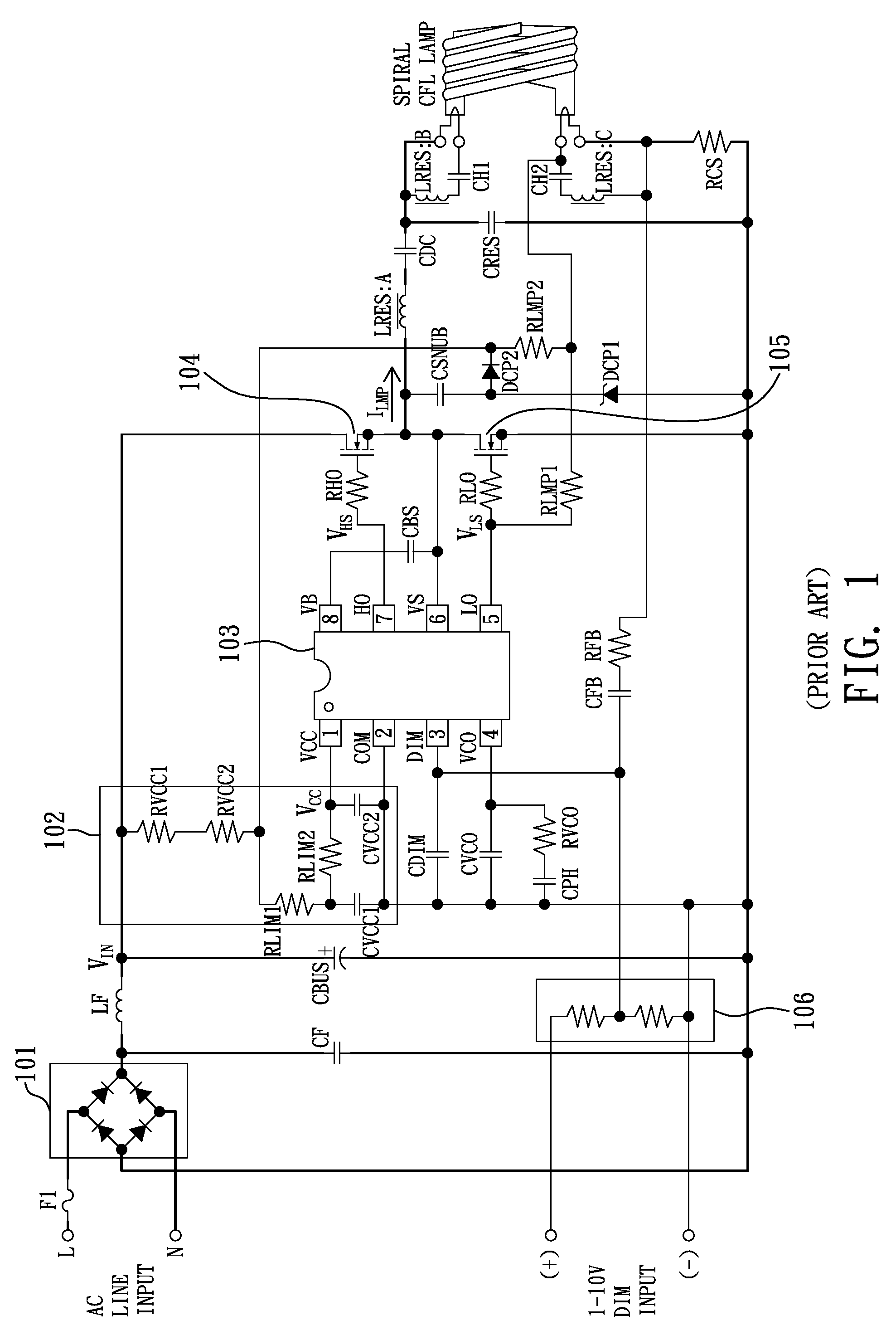
BACKGROUND OF THE INVENTION1. Field of the InventionThe present invention relates to electronic ballasts, and more particularly to electronic ballasts with dimming control from power line sensing.2. Description of the Related ArtIn supplying power to light emitting devices such as fluorescent lamps or cold cathode fluorescent lamps or compact fluorescent lamps, electronic ballasts are widely adopted to keep the lamp current stable.FIG. 1 shows the typical architecture of a prior art electronic ballast with dimming function for driving a fluorescent lamp. As shown in FIG. 1, the prior art electronic ballast with dimming function mainly comprises a full bridge rectifier 101, a VCC start-up circuit 102, a ballast control IC 103, an NMOS transistor 104, an NMOS transistor 105 and a voltage divider 106.In the architecture, the full bridge rectifier 101 is used to rectify an AC line input voltage to generate a main input voltage VIN.The VCC start-up circuit 102, coupling to the main input...

Claims


Application Information

Patent Timeline
Patent Type & Authority Patents(United States)
IPC IPC(8): H05B37/02
CPCH05B41/3921Y10S315/04
Inventor LIN, KO-MINGWANG, YEN-PINGCHEN, PEI-YUANSU, WEI-CHUANHUNG, CHIA-CHIEHLI, JIAN-SHEN
Owner GRENERGY OPTO INC
Learn More