Chassis mounted electric, independent, steering axle of a vehicle

a technology of electric steering axle and chassis, applied in the direction of non-deflectable wheel steering, braking system, transportation and packaging, etc., can solve the problems of poor, or inexistent, lateral control of axle bar location, and the propulsion system significantly increases the ratio of unsprung to sprung weight of the vehicle, so as to shorten the life of electric drive units. , to achieve the effect of reducing the turning radius

Inactive Publication Date: 2011-07-19
NAVISTAR CANADA
View PDF15 Cites 5 Cited by
  • Summary
  • Abstract
  • Description
  • Claims
  • Application Information

AI Technical Summary

Benefits of technology

[0009]Reducing the ratio of unsprung to sprung weight is vital for increasing truck and bus drivability and handling performance because the greater the ratio, the greater the inertia of the suspension, making it unable to respond as quickly to rapid changes in a road surface.
[0011]The inventive chassis-mounted electric, independent, steering—truck axle to be described here provides a significant reduction in the ratio of unsprung to sprung weight in conjunction with independent steering, resulting in improved vehicle handling and performance, an improvement that would be quite beneficial to owners / operators of large commercial vehicles.
[0012]The inventive chassis-mounted electric, independent, steering—truck axle accomplishes these improvements through a combination of independent features that include: mounting the electric motor between the chassis frame rails to remove the contribution of the electric motor from the unsprung weight and removing the wheel brakes from the unsprung weight.
[0013]The inventive chassis-mounted electric, independent, steering—truck axle has a five through eight-link (multi-link) suspension with combinations of coil springs in independent suspension systems for each wheel. Each link performs a specific truck wheel-locating task to ensure constant steering stability and superior handling amid changing road and load conditions while the wheels can move independently of one another. This reduces truck and bus chassis movement on rough surfaces in comparison to walking beam articulations where as much as about eighteen inches is required in known designs while maintaining optimal wheel control at all times.
[0015]Using the inventive chassis-mounted electric, independent, steering—truck axle in both front and rear of a vehicle gives the vehicle all wheel steering (AWS), and hence a reduced turning radius (about 30%) for buses with two steering axles.

Problems solved by technology

Such a design is inherently subject to conditions that include but are not necessarily limited to: axle oscillation when one front wheel hits a bump; gyroscopic torque about the steering axis that tends to turn the axle from left to right when the vehicle is being forwardly propelled; axle inertia amplification of original motion from a road bump; substantial unsprung weight due to a heavy bar that requires heavy linkages and leaf springs (i.e., unsprung weight) for its suspension; wheel misalignment if the axle becomes bent; and poor, or non-existent, lateral control of axle bar location, a significant performance issue.
Such a propulsion system however significantly increases the ratio of unsprung to sprung weight of the vehicle.
Wheel mounted motors are also subject to severe impacts from road bumps during service, and such impacts can significantly shorten the life of these electric drive units.
However, the rear suspension in this vehicle is a heavy, dependent (i.e., non-independent) system, and the axle is a non-steering axle.

Method used


Image

  • Chassis mounted electric, independent, steering axle of a vehicle
  • Chassis mounted electric, independent, steering axle of a vehicle

Examples


Embodiment Construction

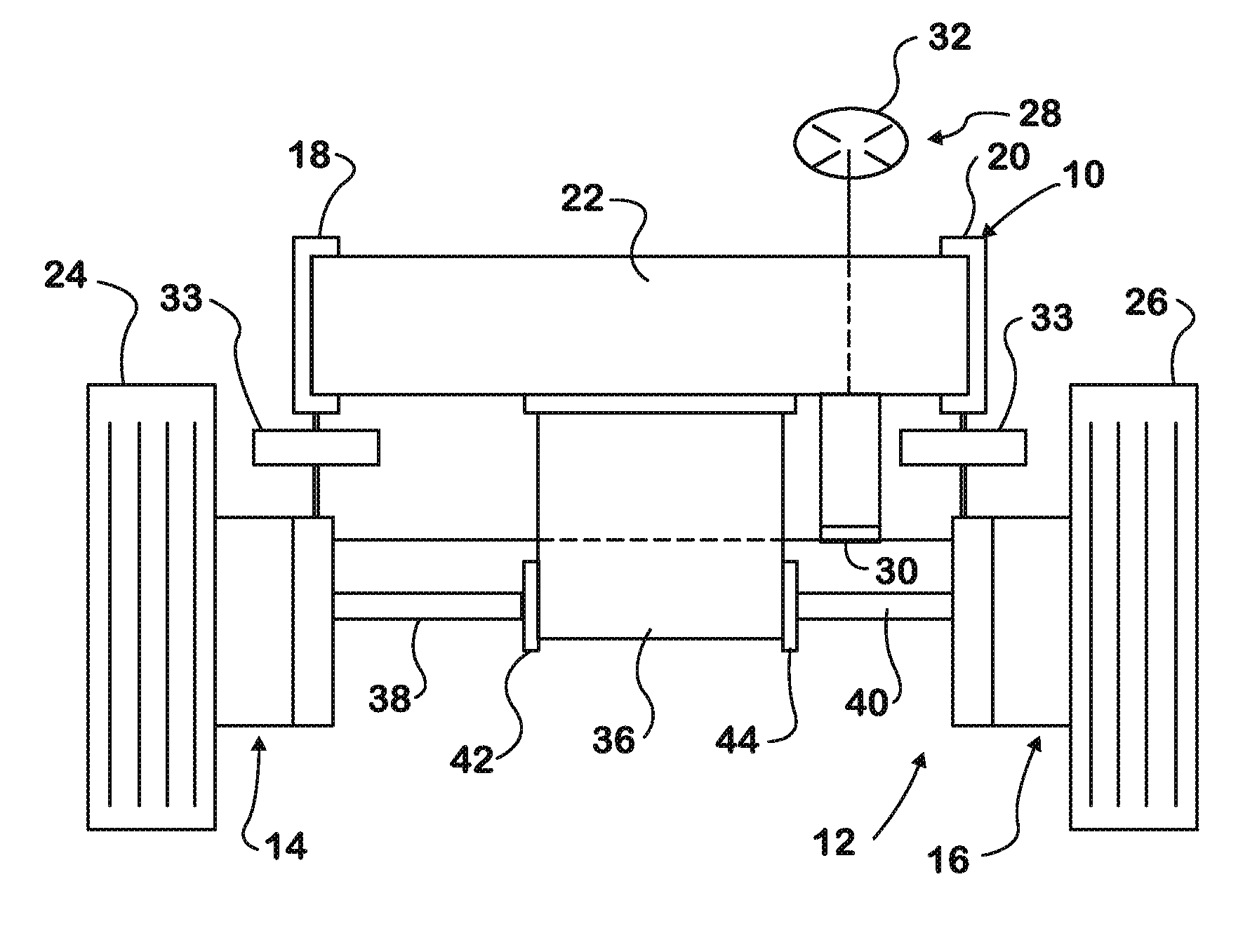
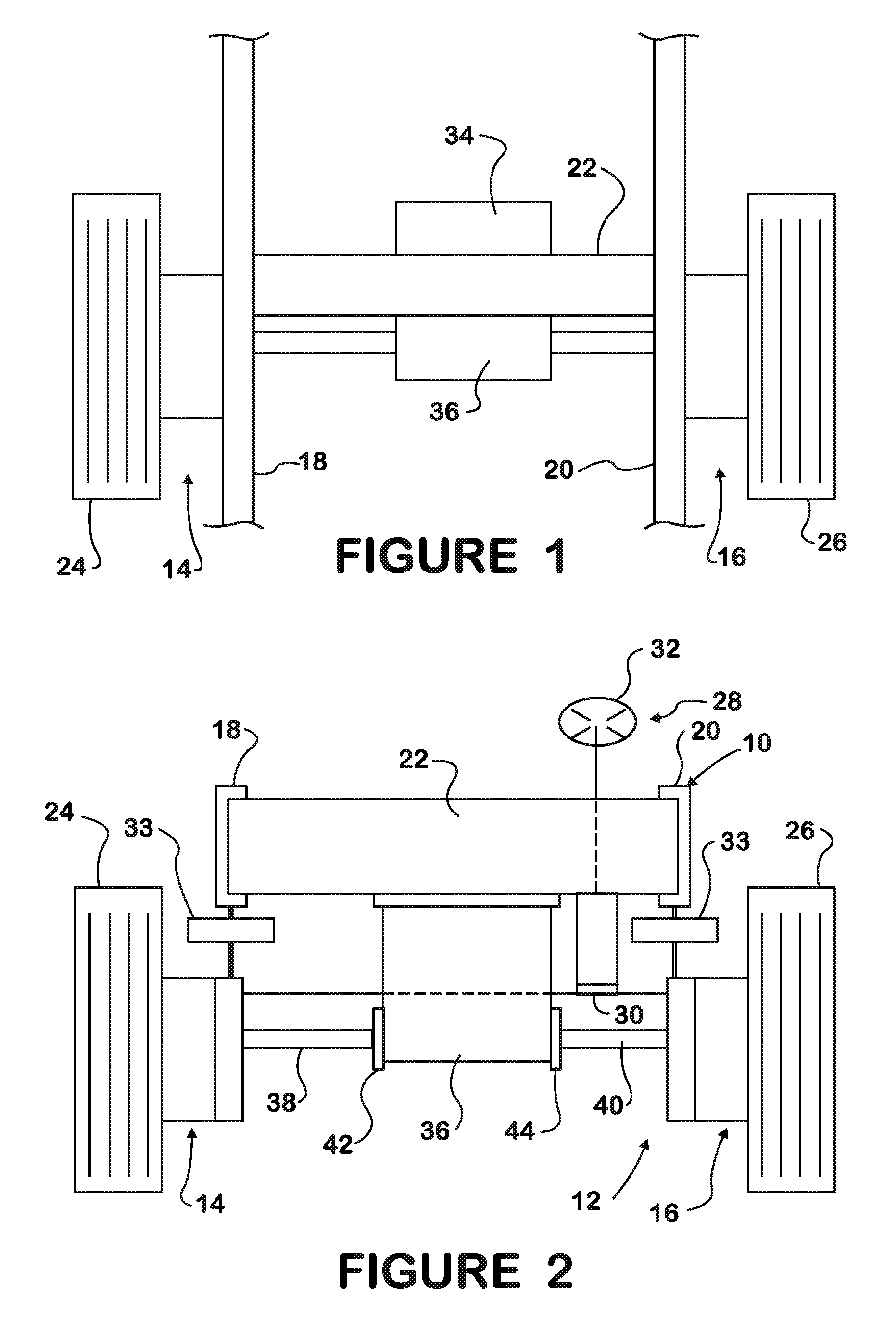
[0020]FIGS. 1 and 2 show a truck chassis frame 10 having an electric, independent, steering axle 12 that comprises right and left wheel units 14, 16 each independently suspended from frame 10. The truck cab that mounts on the chassis frame is not specifically shown.

[0021]Frame 10 comprises right and left side rails 18, 20 running lengthwise of the frame and comprising respective steel channels. Frame 10 comprises one or more cross members at locations along the frame length, such as the one marked 22.

[0022]Right wheel unit 14 comprises a spindle-mounted right wheel 24, and left wheel unit 16, a spindle-mounted left wheel 26. The spindles have journaled mountings in each wheel unit that enable the wheels to turn about respective generally vertical axes as they are being steered by a steering system 28.

[0023]Steering system 28 preferably comprises an electrically assisted rack-in-pinion steering mechanism 30 that is operated by the usual steering wheel 32 within the interior of the ve...


PUM


Abstract

A chassis frame (10) has a cross member (22) that bridges right and left side rails (18, 20). Right and left wheel units (14, 16) comprising respective right and left steered road wheels (24, 26) are suspended from the frame by respective multi-link suspensions (33). A steering system (28) steers the wheels. An electric motor (34) and gear box (36) mounted on the cross member is coupled to the right and left wheels by respective drive shafts (38, 40). The weight of a brake system (42, 44) for the wheels is supported by the frame.

Description

FIELD OF THE INVENTION[0001]This invention relates to wheeled vehicles, especially large trucks and busses.BACKGROUND OF THE INVENTION[0002]Dependent steering axle suspensions have been consistently used in virtually all commercial trucks and buses. Dependent steering axle suspensions physically link right and left steered wheels by a solid cast iron bar (axle) under the front of the vehicle. The bar is suspended from the chassis by heavy leaf springs and shock absorbers.[0003]Such a design is inherently subject to conditions that include but are not necessarily limited to: axle oscillation when one front wheel hits a bump; gyroscopic torque about the steering axis that tends to turn the axle from left to right when the vehicle is being forwardly propelled; axle inertia amplification of original motion from a road bump; substantial unsprung weight due to a heavy bar that requires heavy linkages and leaf springs (i.e., unsprung weight) for its suspension; wheel misalignment if the ax...

Claims


Application Information

Patent Timeline
Patent Type & Authority Patents(United States)
IPC IPC(8): B60K17/00B62D21/00
CPCB60G3/00B60T1/062B60G2200/10B60G2200/18B60G2300/026B60G2300/14B60G2300/50B60Y2200/14B60Y2200/143B60W2540/18
Inventor ORIET, LEO P.BOCANCEA, ANDRE
Owner NAVISTAR CANADA
Why Eureka
Try Eureka