Laminar electrical connector

a technology of laminar electrical connectors and connectors, applied in the direction of coupling contact members, contact members penetrating/cutting insulation/cable strands, printed circuits, etc., can solve the problems of reducing the efficiency of overall connectors and operative lifetimes, and achieves the reduction of overall connector efficiency, reducing the operative lifetime of resulting connectors, and improving connector performance.

Active Publication Date: 2011-07-12
FLEX CABLE
View PDF36 Cites 2 Cited by
  • Summary
  • Abstract
  • Description
  • Claims
  • Application Information

AI Technical Summary

Benefits of technology

[0004]A laminar electrical connector is provided that is formed from multiple superimposed strips of conductive material that form a stack having at least two ends. A second conductive material is used to join adjacent superimposed strips. The resultant connector has ends that are adapted to engage electrical terminals and provide an electrical communication therebetween. The resultant connector lacks a sheath on the ends or a grommet extending through the stack. Such a sheath or grommet limits the operative lifetime of the resulting connector and also creates current focusing that diminishes overall connector efficiency. A connector having a continuous layer of the second conductive material joining adjacent strips along the entire interface between the adjacent strips is also provided and improves connector performance in ways that are especially beneficial to applications associated with an electric vehicle or a hybrid vehicle.
[0005]A process for manufacturing a laminar electrical connector stack includes superimposing strips of a first conductive material having a first material melting temperature to form a stack. A layer of second conductive material having second conductive material melting temperature less than the first conductive material melting temperature is placed between adjacent superimposed strips. Resistive heating of the stack to a temperature greater than two thirds of the second material melting temperature and less than the first conductive material melting temperature increases electrical conductivity and delamination strength of the stack in a direction transverse to the stack.

Problems solved by technology

Such a sheath or grommet limits the operative lifetime of the resulting connector and also creates current focusing that diminishes overall connector efficiency.

Method used


Image

  • Laminar electrical connector
  • Laminar electrical connector
  • Laminar electrical connector

Examples


Embodiment Construction

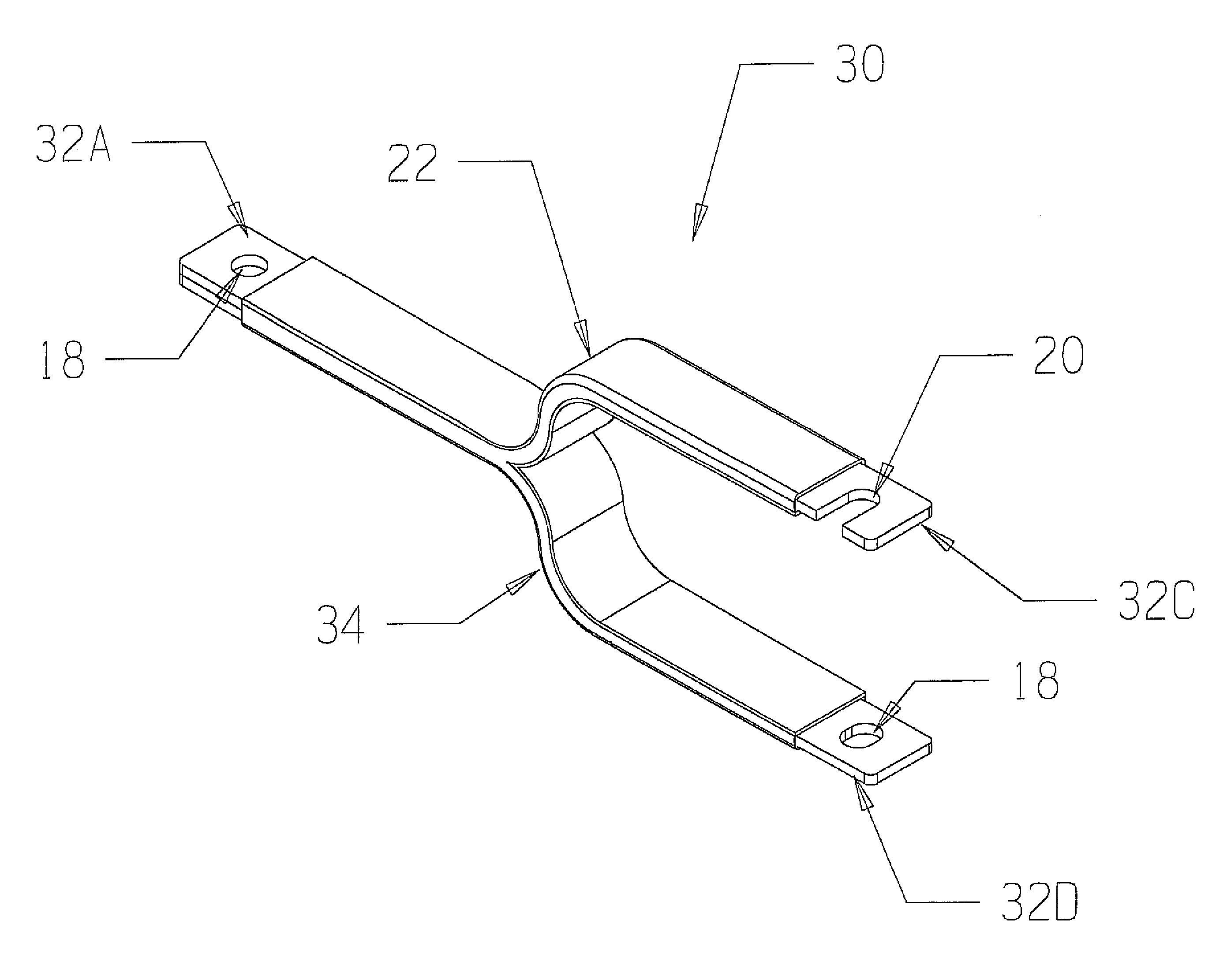
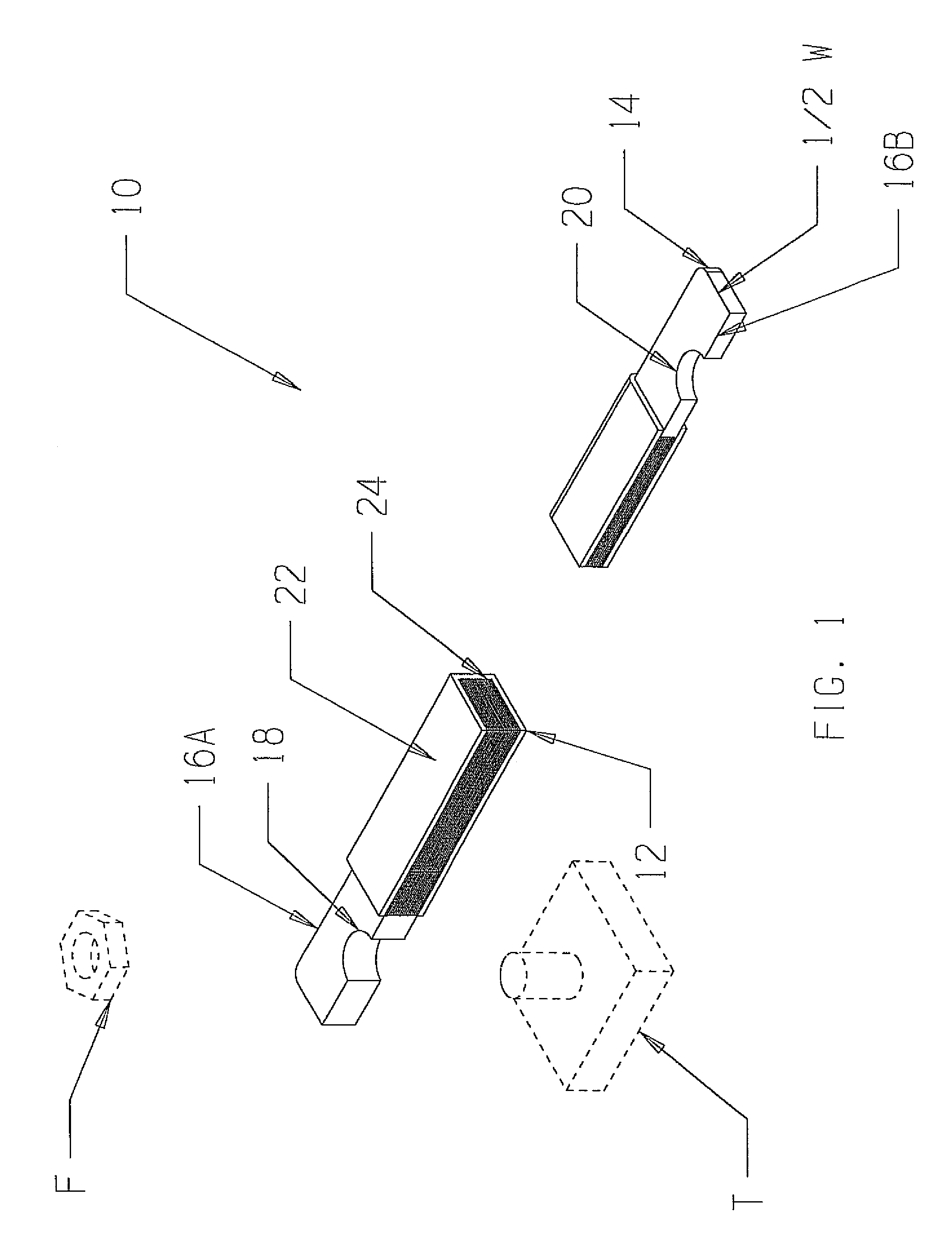
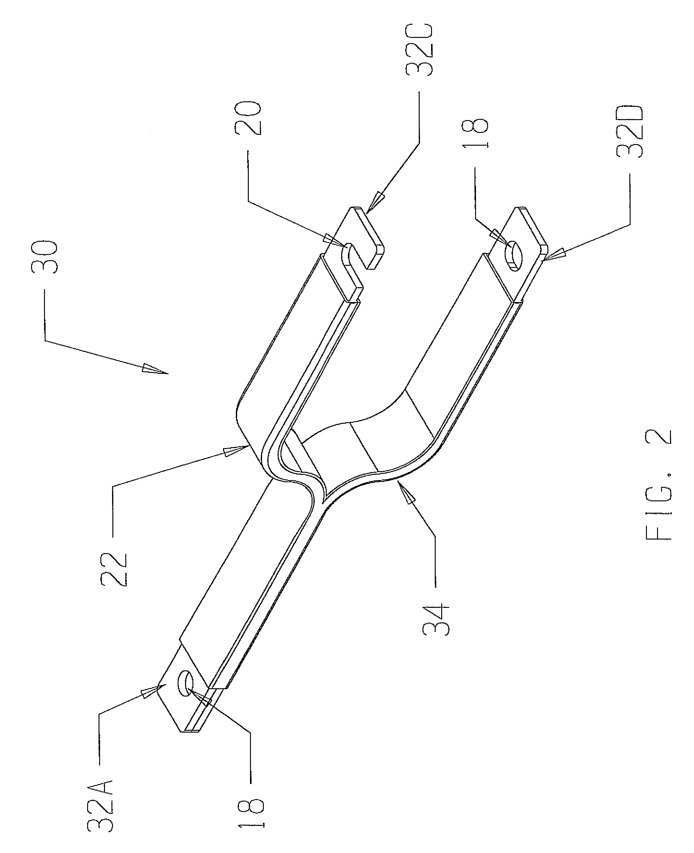
[0008]The present invention has utility as an electrical connector. An inventive connector is particularly well-suited to operate in an environment associated with an electric or hybrid vehicle. Particularly beneficial features of an inventive connector include exclusion of a sheath or grommet surrounding a connector engagement with an extrinsic electrical terminal so as to limit current focusing and mechanical failure associated with the additional sheath or grommet. Additionally, an inventive connector includes layers of a lower melting temperature material relative to the strip material to improve performance of the resultant connector and provide a manufacturing scheme that does not rely on dipping connector ends into molten solder.

[0009]The inventive electrical connector is shown generally at 10 in FIG. 1. The connector 10 is formed from multiple conductive material strips 12 that are superimposed to form a stack 14. The connector 10 has ends at 16A and 16B. The ends 16A and 16...


PUM

PropertyMeasurementUnit
widthaaaaaaaaaa
widthaaaaaaaaaa
thicknessaaaaaaaaaa

Abstract

A laminar electrical connector is provided that is formed from multiple superimposed strips of conductive material that form a stack having at least two ends. A second conductive material is used to join adjacent superimposed strips. The resultant connector has ends that are adapted to engage electrical terminals and provide an electrical communication therebetween. The resultant connector lacks a sheath on the ends or a grommet extending through the stack. Such a sheath or grommet limits the operative lifetime of the resulting connector and also creates current focusing that diminishes overall connector efficiency. A connector having a continuous layer of the second conductive material joining adjacent strips along the entire interface between the adjacent strips is also provided and improves connector performance in ways that are especially beneficial to applications associated with an electric vehicle or a hybrid vehicle.

Description

FIELD OF THE INVENTION[0001]The present invention in general relates to an electrical connector and in particular to a laminar electrical connector having improved terminal conductivity and longevity.BACKGROUND OF THE INVENTION[0002]Electrical connectors have long been made from superimposed plates or strips of conductive metal representative of these articles of those detailed in U.S. Pat. Nos. 710,532; 1,588,556; 2,074,810; and 2,092,505. The common characteristic of these earlier connectors is the inclusion of a sheath or grommet surrounding the hole in the connector, the hole engaging an electrical terminal. Securement of such a connector between two electrically insulated regions allowed these connectors to convey electrical current between the terminals. While prior art connections were well suited for a number of uses, technical innovations associated with electric and hybrid powered vehicles have created performance demands that existing electrical connectors are unable to s...

Claims


Application Information

Patent Timeline
Patent Type & Authority Patents(United States)
IPC IPC(8): H01R11/20
CPCH01R13/03Y10T29/49208
Inventor KROULIK, ERWIN
Owner FLEX CABLE
Why Eureka
Try Eureka