Doherty power amplifier
a power amplifier and doherty technology, applied in the direction of amplifiers, amplifier types, amplifiers with semiconductor devices/discharge tubes, etc., can solve the problems of inability to meet the requirements of above-mentioned conventional techniques, failure to present satisfactory solutions, etc., to achieve the advantage of efficiency and linearity, miniaturization and integration
- Summary
- Abstract
- Description
- Claims
- Application Information
AI Technical Summary
Benefits of technology
Problems solved by technology
Method used
Image
Examples
first embodiment
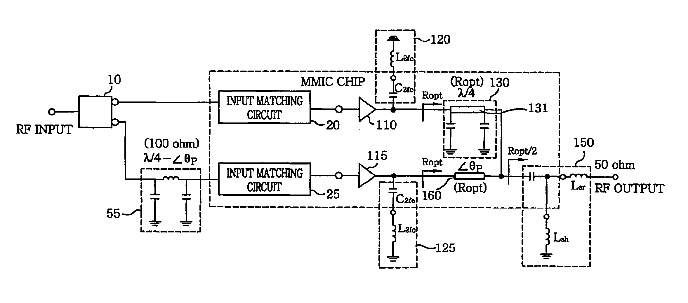
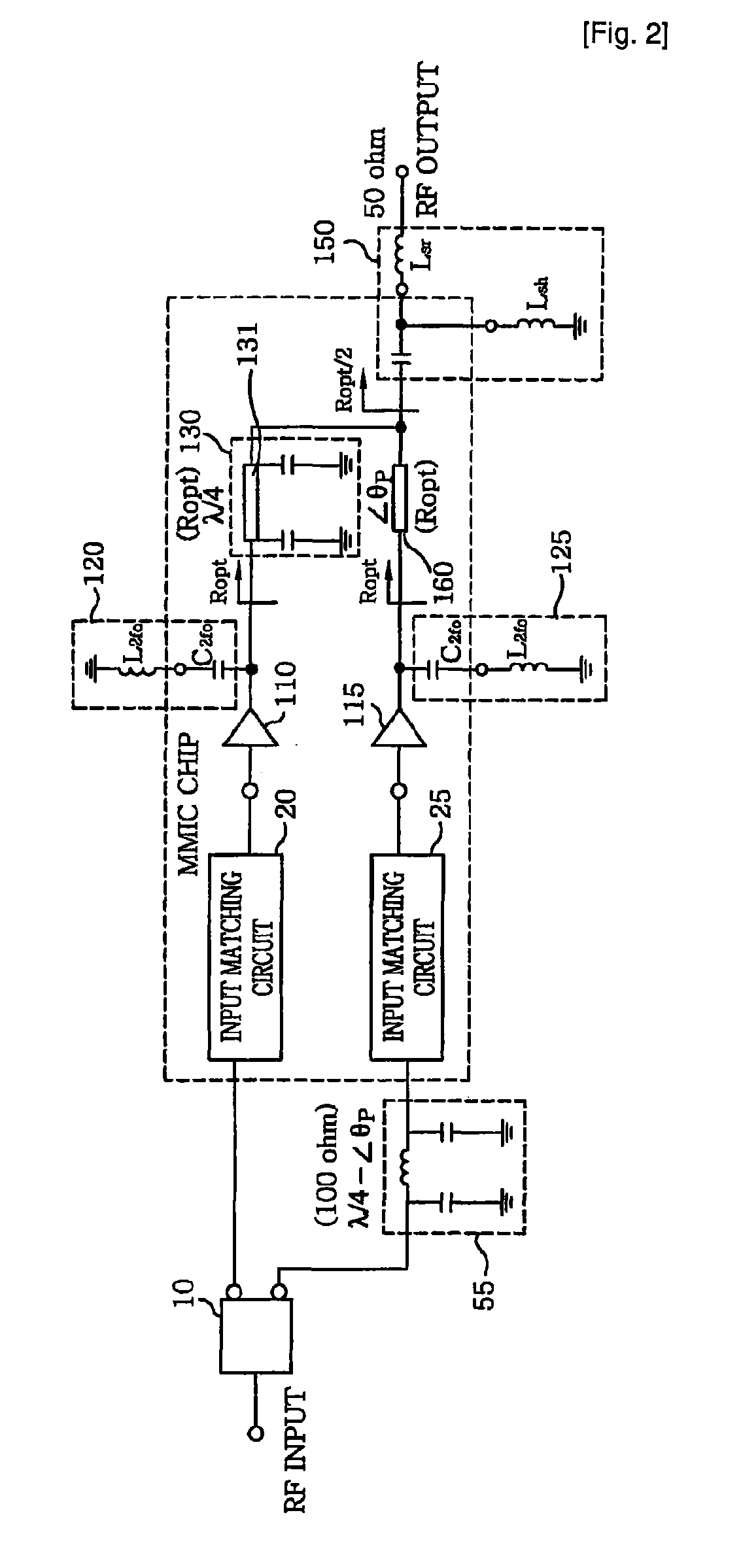
[0026]FIG. 2 illustrates a circuit diagram of a Doherty amplifier employing an output matching method in accordance with the present invention. Herein, identical reference numerals designate the same elements in comparison with FIG. 1.
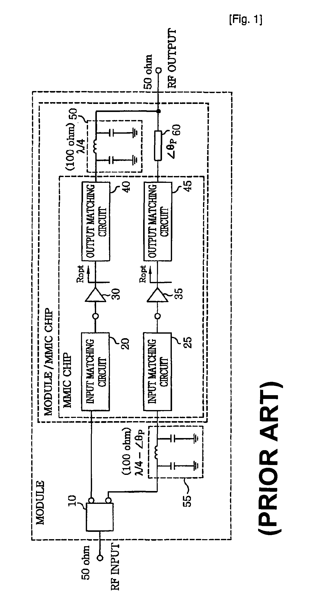
[0027]If a quarter-wave transformer for controlling a load line impedance of a carrier amplifier in a Doherty amplifier is configured with a λ / 4 π-network composed of at least one inductor(s)(L) and at least one capacitor(s)(C) as shown in FIG. 1, it has drawbacks in terms of the chip size and power loss at the passive devices. In this case, one important factor is the inductance. In a conventional Doherty amplifier shown in FIG. 1, a characteristic impedance of the quarter-wave transformer arranged at an output end of the carrier amplifier is equal to 100 Ohm. Further, the inductance corresponding thereto is obtained by the equation of L=Z0 / ω0. As seen therefrom, the quarter wave transformer can be implemented by using an inductor of a smaller inducta...
second embodiment
[0035]FIG. 3 provides a circuit diagram of a Doherty amplifier employing the input matching method in accordance with the present invention. Herein, identical reference numerals designate the same elements in comparison with FIG. 2.
[0036]Referring to FIG. 3, the Doherty amplifier of the present embodiment includes a plurality of output matching circuits 40 and 45; a λ / 4 π-network 50; a carrier and a peaking amplifier 110 and 115; a second delay circuit 140; a power dividing circuit 145; an offset line 160; and a plurality of input matching circuits 170 and 175. More specifically, the carrier and the peaking amplifier 110 and 115 are arranged in parallel, and the output matching circuits 40 and 45 are connected to output ends of the carrier and the peaking amplifier 110 and 115, respectively. The λ / 4 π-network 50 is connected, as an impedance control circuit, to an output end of the output matching circuit 40 arranged at an output end of the carrier amplifier 110 for adjusting a load...
third embodiment
[0039]FIG. 4 illustrates a circuit diagram of a Doherty amplifier in accordance with the present invention, to which both the input and the output matching method of the present invention are applied. Herein, identical reference numerals designate the same elements in comparison with FIGS. 2 and 3.
[0040]Referring to FIG. 4, the Doherty amplifier in accordance with the third embodiment of the present invention includes a carrier amplifier 110; a peaking amplifier 115; an impedance control circuit 130; a second delay circuit 140; a power dividing circuit 145; an output matching circuit 150; and a plurality of input matching circuits 170 and 175. The carrier amplifier 110 and the peaking amplifier 115 are arranged in parallel, and the input matching circuits 170 and 175 are connected to input ends of the carrier and the peaking amplifier 110 and 115, respectively. The impedance control circuit 130 is connected to an output end of the carrier amplifier 110 for adjusting the load line im...
PUM
 Abstract
Description
Claims
Application Information
 - R&D
- Intellectual Property
- Life Sciences
- Materials
- Tech Scout
- Unparalleled Data Quality
- Higher Quality Content
- 60% Fewer Hallucinations
Browse by: Latest US Patents, China's latest patents, Technical Efficacy Thesaurus, Application Domain, Technology Topic, Popular Technical Reports.
© 2025 PatSnap. All rights reserved.Legal|Privacy policy|Modern Slavery Act Transparency Statement|Sitemap|About US| Contact US: help@patsnap.com


