
LED assembly

a technology of leds and assemblies, applied in the field of led assemblies, can solve the problems of poor environmental protection, low contrast performance, and poor performance of outdoor leds, and achieve the effects of less environmental influence, easy treatment, and convenient watertightness

Inactive Publication Date: 2011-07-05
BARCO NV
View PDF5 Cites 17 Cited by
  • Summary
  • Abstract
  • Description
  • Claims
  • Application Information

AI Technical Summary

Benefits of technology

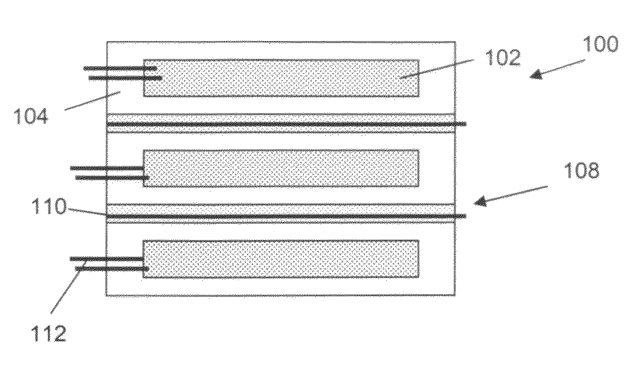
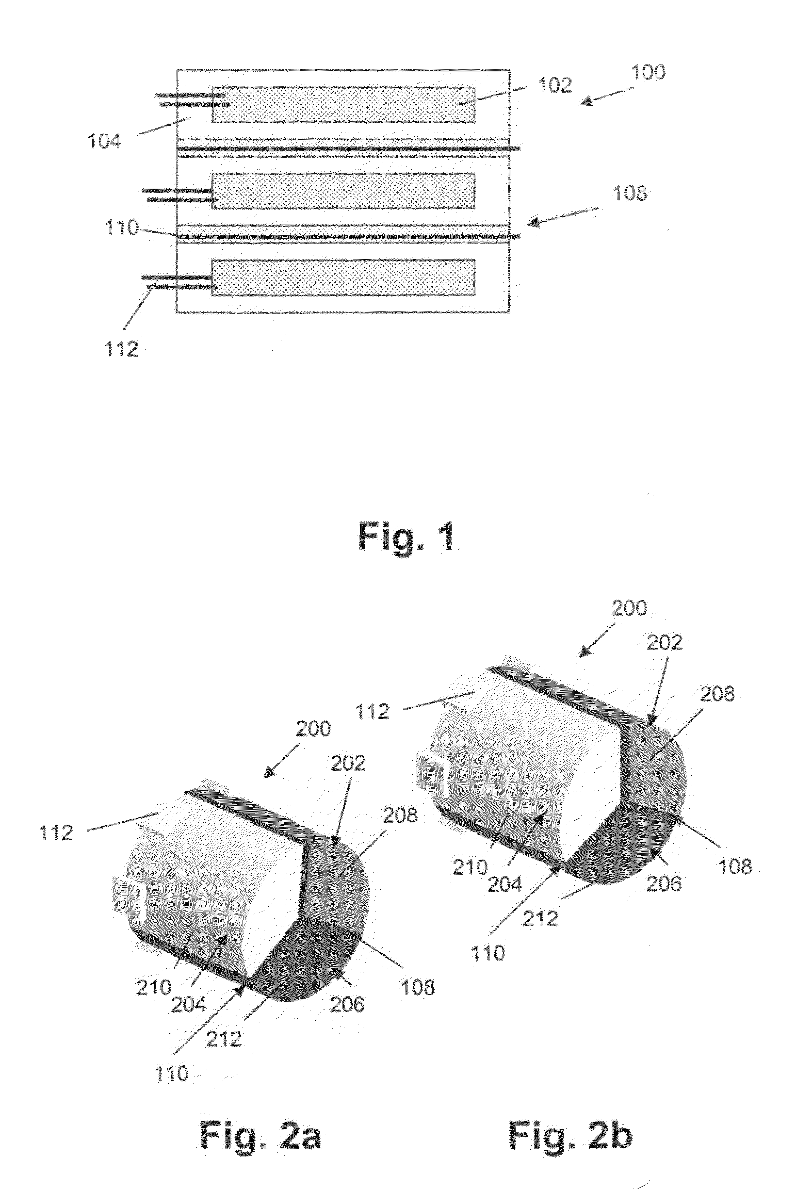
The present invention provides a light emitting device assembly with multiple lamp-type light emitting devices that have high brightness and good color compound performance. The LED assemblies combine high brightness and good color compound performance in a compact design that allows for high pitch systems. The LED assemblies have a good viewing angle and high contrast, making them suitable for indoor applications. The plurality of light emitting devices can be directly or indirectly connected to each other, and the connection can be made through a light separation means to avoid crosstalk between devices. The LED assemblies can be shaped and positioned so that the light output sides or surfaces are substantially adjacent or neighboring to each other, and the spacing between the light output sides or surfaces is smaller than the average diameter of the area of the light output surface of a single lamp-type light emitting device. The invention also provides a display or lighting system comprising the light emitting device assembly and a method for manufacturing the assembly.

Problems solved by technology

The SMD LEDs are becoming more efficient, but still provide only mediocre performance for outdoor use even when driven at high drive current.
Often a white package is used to increase light output, but this yields lower contrast performance.
SMD-type LEDs are not suitable for exposure to environmentally harsh conditions like rain, frost and extreme heath.
Using an SMD LED as a light source in outdoor circumstances therefore is less appropriate due to its vulnerability to water-intrusion and failure due to water-leakage.
The lamp-type LEDs have the disadvantage that, since they are single color LEDs, they cannot be mounted very close together, yielding low color compound performance.

Method used


Image

  • LED assembly
  • LED assembly
  • LED assembly

Examples


Embodiment Construction

[0035]The present invention will be described with respect to particular embodiments and with reference to certain drawings but the invention is not limited thereto but only by the claims. The drawings described are only schematic and are non-limiting. In the drawings, the size of some of the elements may be exaggerated and not drawn on scale for illustrative purposes. The dimensions and the relative dimensions do not correspond to actual reductions to practice of the invention. Furthermore, the terms first, second, third and the like in the description and in the claims, are used for distinguishing between similar elements and not necessarily for describing a sequence, either temporally, spatially, in ranking or in any other manner. It is to be understood that the terms so used are interchangeable under appropriate circumstances and that the embodiments of the invention described herein are capable of operation in other sequences than described or illustrated herein. It is to be no...


PUM


Abstract

The present invention relates to a light emitting device assembly. Such a LED assembly comprises a plurality of lamp-type light emitting devices, each of said lamp-type light emitting devices having a light output side and side walls. The plurality of lamp-type light emitting devices are directly or indirectly connected to each other via said side walls. The latter allows to obtain a compact LED assembly with high brightness.

Description

TECHNICAL FIELD OF THE INVENTION[0001]The present invention relates to the field of lighting, projection and displaying. More particularly, the present invention relates to light emitting devices, projectors, displays and lighting systems using such light emitting devices and methods for manufacturing and operating these.BACKGROUND OF THE INVENTION[0002]Light emitting devices (LEDs), such as for example light emitting diodes, are used in displays for indoor and outdoor use. LED displays thereby aim at combining high light output and high resolution. Combining those properties requires a specific LED type approach. Different LED types exist. Surface mounted device-type (SMD-type) LEDs are LEDs that are mounted directly onto the surface of a printed circuit board. Lamp-type LEDs are LEDs whereby the light emitting device is mounted in a lamp housing.[0003]For high resolution displays, often surface mounted devices (SMD) three-in-one LEDs are used. These LEDs combine three surface-moun...

Claims


Application Information

Patent Timeline
Patent Type & Authority Patents(United States)
IPC IPC(8): F21S4/00F21K99/00H01L33/54
CPCF21K9/00G09F9/33F21Y2105/001F21Y2101/02H01L33/54F21Y2105/10F21Y2115/10
Inventor MEERSMAN, KARIMDEVOS, BRUNOGERETS, PETERNOYELLE, KATRIEN
Owner BARCO NV
Learn More