[0006]The primary object of the present invention is to provide a time-saving clamping assembly that is able to accommodate the differing upper edge configurations and thickness dimensions of a variety of plastic and metal fluid collection pans commonly used in fluid overflow prevention applications. It is also an object of the present invention to provide a clamping assembly that has the type of simple cost-effective construction and assembly needed for widespread distribution and use. A further object of the present invention is to provide a clamping assembly designed for prompt and cost-effective installation. It is also an object of the present invention to provide a clamping assembly that is adjustable for secure installation of a float switch and allowing the originally established orientation of the float switch to be substantially maintained during its entire period of use. Another object of the present invention is to provide a clamping assembly with a design that compensates for insubstantial condensate collection pan construction and overcomes lean in problems that could adversely change the orientation of a mounted float switch body and diminish the reliability of its operation. In addition, it is a further object of the present invention to provide a clamping assembly that is made from corrosion-resistant materials capable of resisting premature deterioration and malfunction for long duration use.
[0007]As described herein, properly manufactured and used, the present invention would provide a clamping assembly for mounting a float switch in a secure and fixed position of use relative to a fluid collection pan or other fluid collection container, wherein after mounting the float switch will be able to promptly, reliably, and repeatedly shut-off the flow of condensate or other fluid into the associated pan or container when the amount of fluid collected therein exceeds a pre-determined maximum depth considered safe. Further, its inverted J-shaped slot allows the present invention clamping assembly to be successfully used with fluid collection containers having differing upper edge, lip, and flange configurations and different wall thickness dimensions. The present invention is typically made from plastic, and is thereby impervious to corrosion, which in combination with its sturdy construction avoids premature deterioration and / or malfunction. Also, it has a two-part structure and simple assembly, wherein the front and back clamping members are joined together to form an inverted J-shaped slot that contains the upper edge, lip, or flange of a fluid collection pan during clamping assembly use. Use of one fastener is typically sufficient to join the front and back clamping members together when it is employed in a central position near their top surfaces. Furthermore, a thumbscrew having an oversized head configured for easy hand manipulation is preferred as it facilitates and expedites clamping assembly installation. The use of an oversized thumbscrew also expedites separation of front and back clamping members from one another, when needed. Further, the use of a fastener for joining the front and back clamping members of the present invention to one another prevents the need for drilling any holes in a pan wall for float switch mounting, saving time and making the installation of a fluid level monitoring float switch via use of the present invention both efficient and cost-effective. Furthermore, the design of the present invention clamping members includes a plurality of vertically-extending ribs and at least two horizontally-extending posts that in combination provide sturdy construction that help to overcome insubstantial construction in a fluid collection pan wall, when encountered. In addition, the inverted J-shaped slot of the present invention and the use of oversized thumbscrews can provide an adjustable (but quickly made) and secure connection of the present invention clamping assembly to a wide variety of pan walls even though they have different upper edge, lip, or flange configurations, different wall thickness dimensions, and inconsistent wall thickness variation, as the large surface area contact provided for the pan wall within the inverted J-shaped slot compensates for weak pan wall construction to prevent lean in and adverse change in float body orientation that could potentially cause slower and / or sporadic shut-off signal generation. The use of an integral rail plate in association with the exterior surface of the front clamping member also facilitates and expedites the mounting of a float switch to a fluid collection pan for fluid-monitoring purposes, while also making the connection secure so that performance-reducing changes in the after-installation orientation of the float switch will not be experienced.
[0008]Although the description herein provides preferred embodiments of the present invention, it should not be construed as limiting the scope of the present invention clamping assembly. For example, variations in the size, location, number, and spaced-apart location of the multiple thumbscrew openings in the back clamping member; the depth and width dimensions of the substantially linear portion of the inverted J-shaped slot; the number, location, configuration, and relative spacing of the vertically-extending ribs on the front and back clamping members; the comparative height dimensions of the front and back clamping members; the configuration and dimension of the thumbscrew or other means used to join the front and back clamping members; in addition to those variations shown and described herein, may be incorporated into the present invention. Thus, the scope of the present invention should be determined by the appended claims and their legal equivalents, rather than being limited to the examples given.
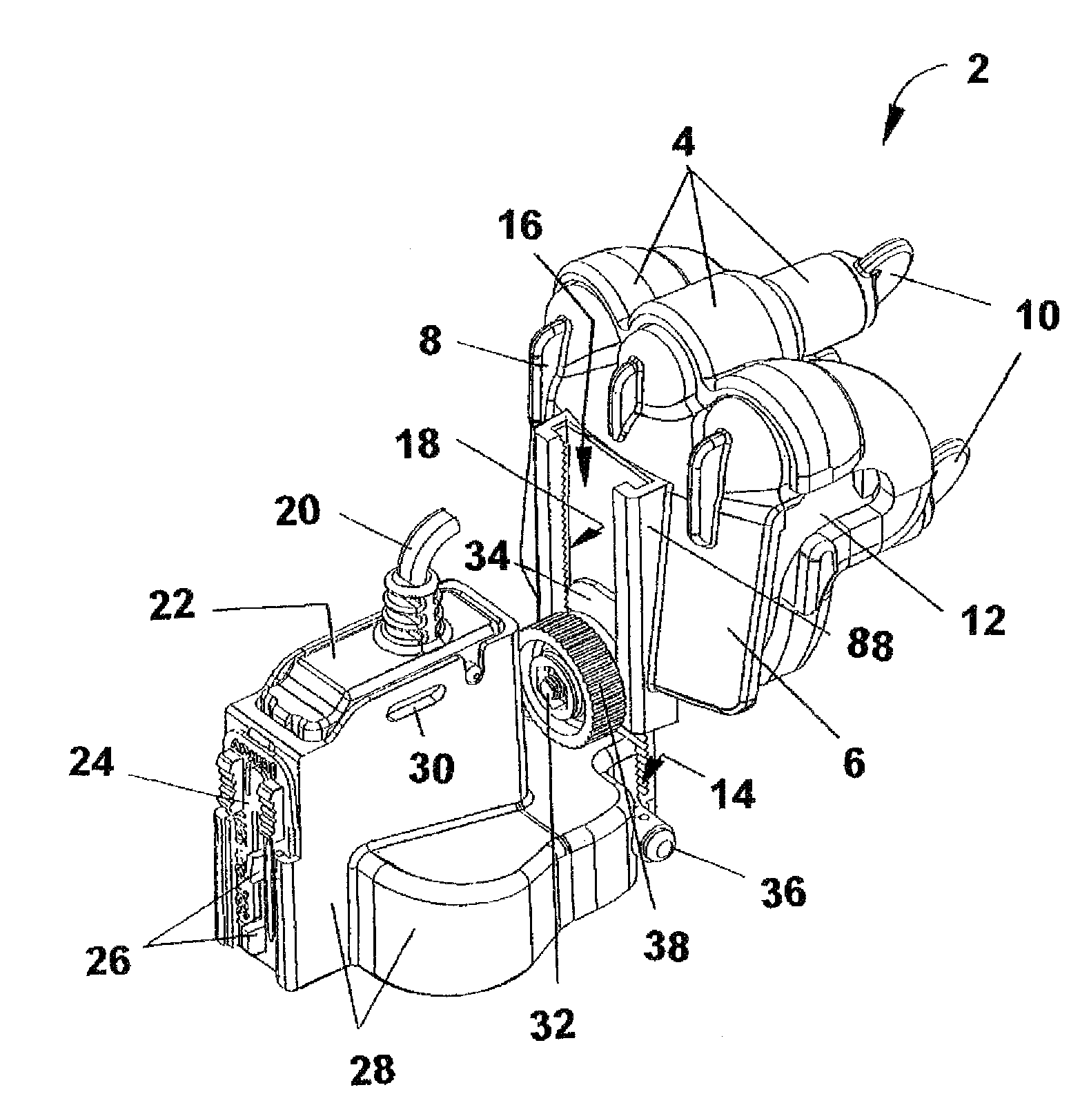
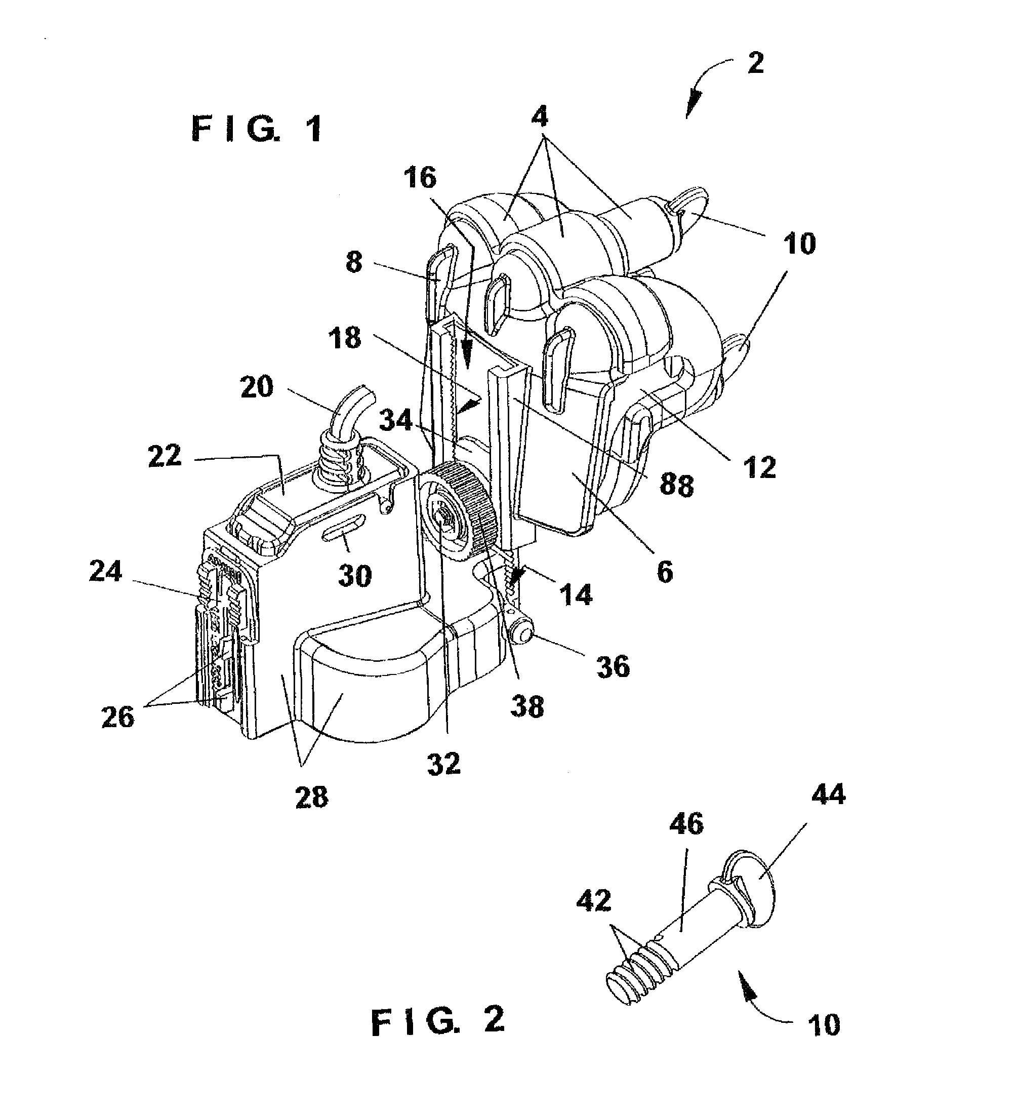
[0009]FIG. 1 is a perspective view of the most preferred embodiment of the present invention having a two-part structure with front and back clamping members connected together via a single thumbscrew, with at least one other thumbscrew used to secure the back clamping member against the exterior surface of a fluid collection pan, and also with the front clamping member having an integral rail plate, a float switch housing securely but adjustably fixed to the rail plate via an easily hand-manipulated lock-nut having a grooved outer surface, and the float switch housing supporting a micro switch that can be configured for electrical connection to a fluid-producing unit or system to send it a shut-off signal when rising fluid in an associated fluid collection pan exceeds a pre-determined level considered safe.
[0010]FIG. 2 is perspective view of one configuration of thumbscrew that can be successfully used as a part of the most preferred embodiment of the present invention to join front and back clamping members together, and also to secure the back clamping member against the exterior surface of an associated fluid collection pan while the pan's upper edge, lip, or flange is inserted within the inverted J-shaped slot formed when the front and back clamping members are joined together, with the thumbscrew shown having an elongated configuration and an enlarged head of adequate size for easy hand-manipulation.
[0011]FIG. 3 is a perspective view of the exterior surface of the front clamping member used as a part of the most preferred embodiment of the present invention, which in its position of use is secured against the interior surface of the wall of a fluid collection pan having its upper edge, lip, or flange inserted within the inverted J-shaped slot formed between the front and back clamping members when they are joined together, with the exterior surface of the front clamping member also shown to have several vertically-extending external strengthening ribs near its top surface and a centrally positioned integral rail plate, with the rail plate having a slot with an open-front configuration and a vertically-extending ridged surface adjacent to the left side of the open-front configuration of the slot.


