
Shortened dipole and monopole loops

a dipole loop and monopole technology, applied in the field of dipole loops, can solve the problems of shortening such aerials mechanically, further considerable outlay, and reducing the monopole effect, and achieves the effects of good properties, good properties, and adequate radiation resistan

Inactive Publication Date: 2005-09-20
SYNERGY MICROWAVE CORP
View PDF4 Cites 6 Cited by
  • Summary
  • Abstract
  • Description
  • Claims
  • Application Information

AI Technical Summary

Benefits of technology

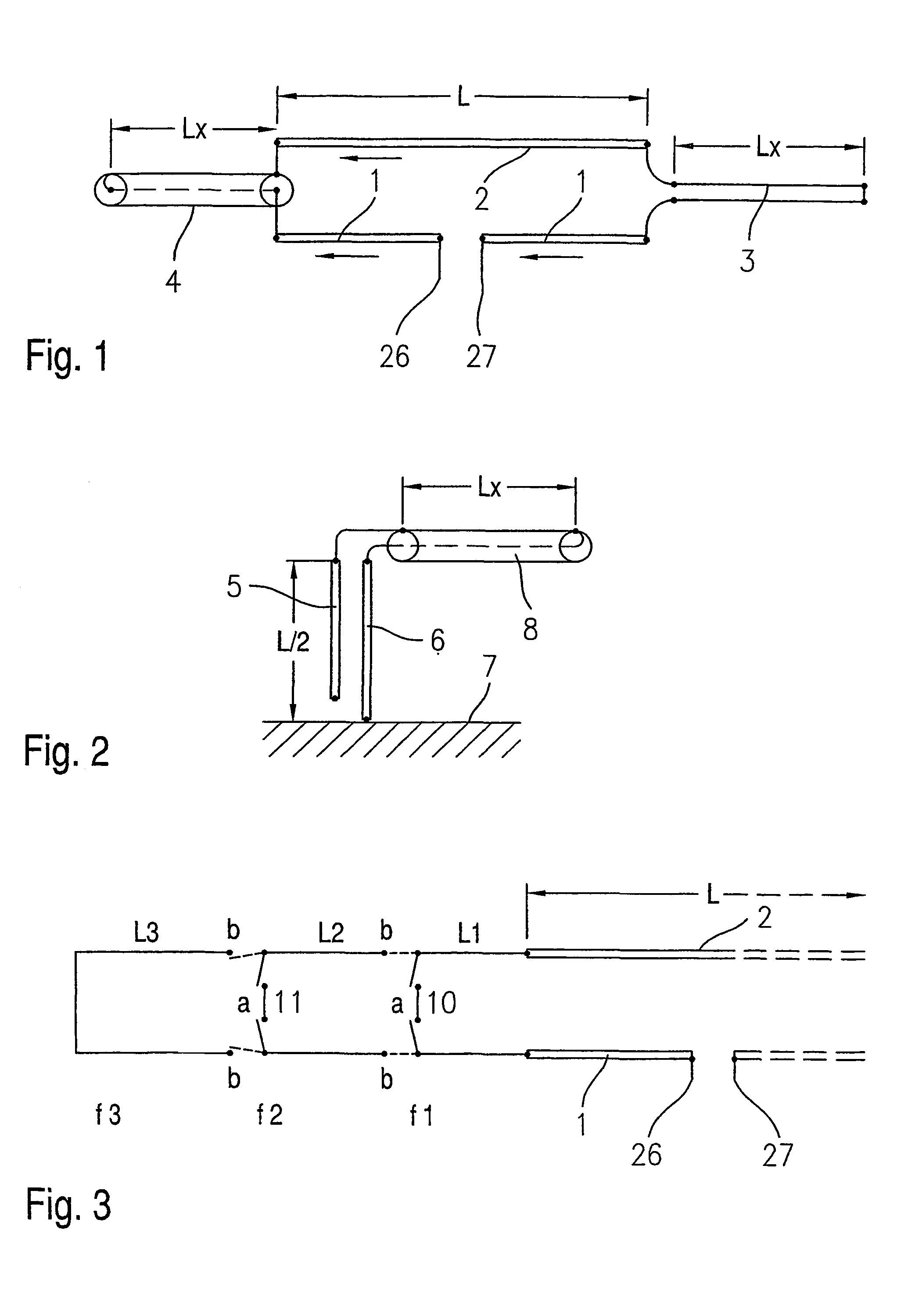
[0008]A dipole or monopole loop according to the invention can be greatly shortened, for example to only 5 to 6% of the operational wavelength at the lowest operational frequency, so the mechanical length of a dipole loop for an operational frequency of 1.5 MHz is equal to a mechanical length of only 10 to 12 meters. In spite of this the radiation resistance is still adequately great and greater than 10 ohms. Therefore a dipole loop of this kind according to the invention has almost equally good properties as a normal lamda / 2 dipole. Tests have shown that the efficiency of the emitting aerial part of an aerial according to the invention is also more than 50% at 1.8 MHz and more than 80% at 3.6 MHz without loss of matching elements and earth losses, in other words in this respect too equally good properties as with a lamda / 2 dipole are achieved. In spite of this, the dipole or monopole loop according to the invention can be constructed very simply and cost-effectively, as only one non-emitting conductor piece of appropriate length is placed on the ends. Geometrically complicated roof capacities in the form of stretched out wires or complicated shortening coils in the dipole are avoided. The use of a non-emitting conductor piece for compensating the shortening of the emitter is also particularly advantageous owing to the small losses of such conductor pieces. The arrangement according to the invention is also especially suitable for the construction of multi-band aerials, which can easily by switched over in frequency. A vertical dipole according to the invention can also still generate even radiation at relatively low frequencies owing to its small length. The field strength of the aerial in the near field is therein relatively low downwards, so the strict regulations for operating such transmitting aerials can easily be complied with.
[0009]The principle according to the invention can be applied in all the normal known forms of dipole and monopole loops, both with simple emitting dipoles and with reflectors or directors of more complex aerial arrangements and also with logarithmic-periodic aerials which are constructed with dipole or monopole loops of this kind. Existing aerials can also be supplemented or converted with little outlay according to the principle according to the invention. As the switchover devices assigned to the non-emitting conductor pieces can easily be remote-controlled, an aerial consisting of several dipole loops can be tuned not only to optimal radiation resistance, but also to an optimal reflection factor or direction factor.

Problems solved by technology

A conventional lambda / 2 aerial would consequently have a length of approximately 100 meters, the implementation of which as a horizontal or vertical aerial means a considerable mechanical outlay.
It is known to shorten such aerials mechanically with respect to their theoretical length and to balance the associated disadvantage in efficiency by suitable measures, such as roof capacities and / or series inductivities, but these known solutions also require a further considerable outlay, especially with, an aerial in multi-band operation.

Method used


Image

  • Shortened dipole and monopole loops
  • Shortened dipole and monopole loops
  • Shortened dipole and monopole loops

Examples


Embodiment Construction

)

[0015]The invention is explained in detail below using embodiment examples with the aid of schematic drawings.

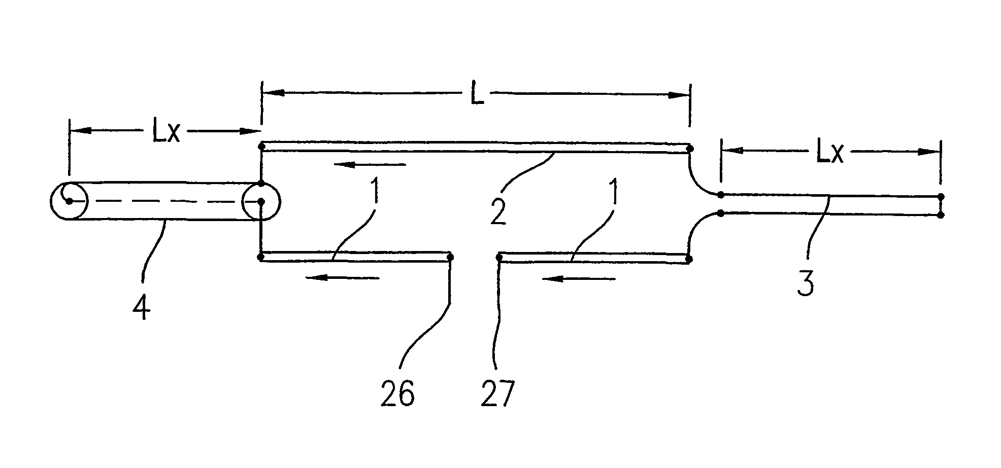
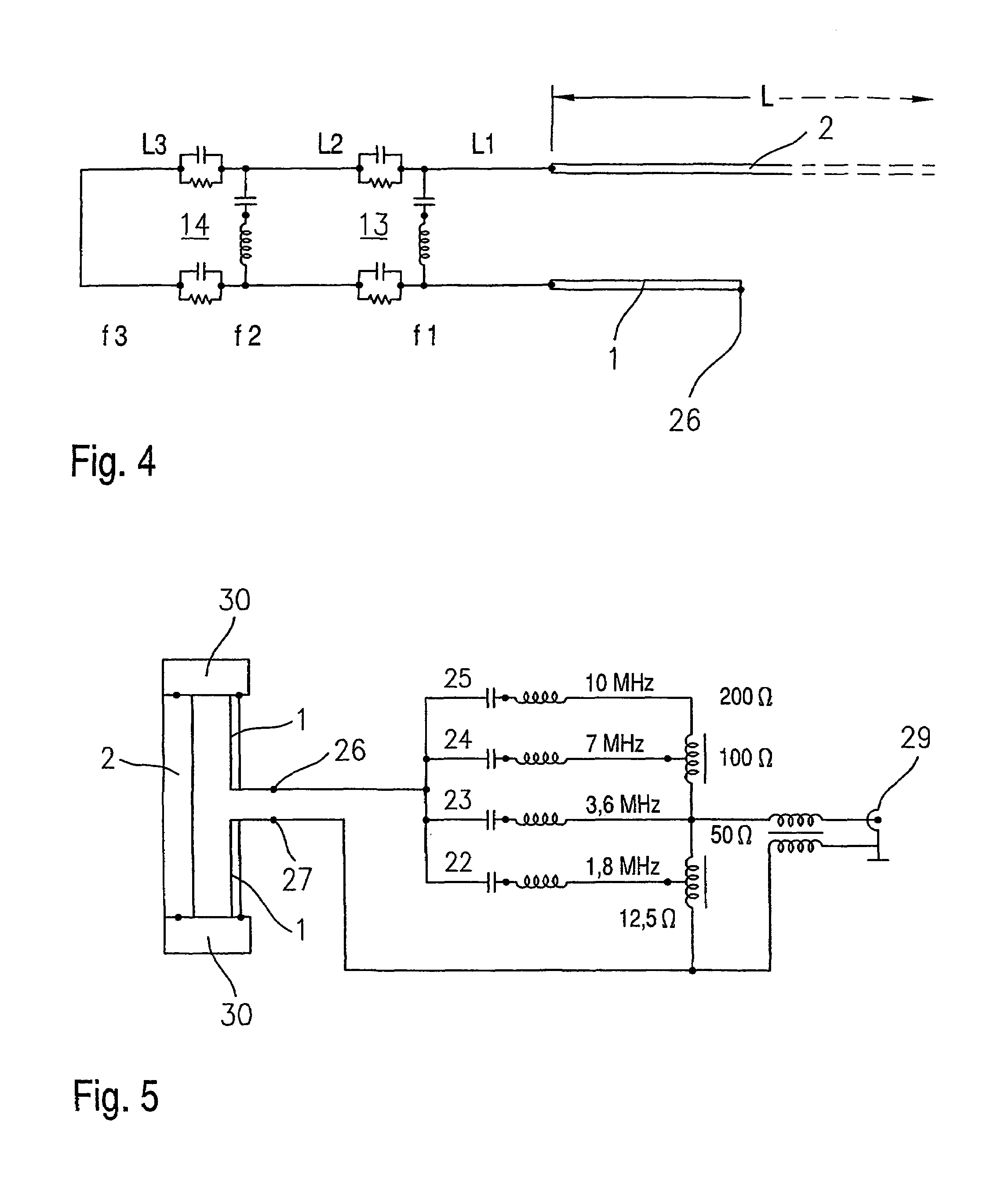
[0016]FIG. 1 shows schematically a dipole loop according to the invention operated as a horizontal emitter. It consists of two parallel dipole emitters 1 and 2, much shortened compared to the theoretical length lamda / 2, which are arranged parallel next to one another at a short distance of less than lamda / 20 and of which only one dipole emitter 1 is fed in the centre. The mechanical length L of these two dipole emitters 1, 2 is equal, for example, to only 6% of the operational wavelength lamda; for the lower threshold frequency of 1.5 MHz of the threshold wave range this means a mechanical length of only L=12 meters. To both ends of these dipole emitters 1, 2 a non-emitting conductor piece is connected in each case, this being either in the form of a parallel wire overhead line 3, as illustrated for the right end of the dipole, or in the form of a non-symmetrical coaxial ca...


PUM


Abstract

The invention relates to dipole and monopole loops with a much shortened emitter relative to the theoretical length thereof and electrically extended at the ends thereof by non-emitting conductor pieces.

Description

BACKGROUND[0001]1. Field of the Invention[0002]The invention relates to a dipole loop (folded dipole) or monopole loop.[0003]2. Description of the Related Art[0004]A dipole loop or folded dipole consists of two closely adjacent lambda / 2 dipoles, connected at the ends, but only one of which is fed. The same current direction is set on the dipoles. Both dipoles support one another in their action. By means of different thicknesses of the two dipoles the input impedance can be influenced via transformatory effects. A so-called monopole loop, which can be interpreted as a half dipole loop on a conducting plane and consists of two lamda / 4 long dipoles, which again are arranged closely adjacent and are connected to one another at the upper end, acts on the same principle. Dipole or monopole loops of this kind on a conducting plane are used as transmitting and receiving aerials in the short- and ultra-short-wave range in various embodiments.[0005]Radio operation is also carried out in the ...

Claims


Application Information

Patent Timeline
Patent Type & Authority Patents(United States)
IPC IPC(8): H01Q9/42H01Q9/04H01Q9/36H01Q9/26H01Q3/24H01Q5/00H01Q5/10H01Q5/321H01Q7/00
CPCH01Q9/26H01Q9/36H01Q9/42
Inventor ROHDE, ULRICH L.DANZEISEN, KLAUS
Owner SYNERGY MICROWAVE CORP
Learn More