
Delivery pipe for the transport of solids

a technology for solids and pipes, applied in the direction of flexible pipes, rigid pipes, pipes, etc., can solve the problems of increased wear on the inlet side, disproportionately high wear, and the effect of increasing the service li

Inactive Publication Date: 2011-06-28
ESSER WERKE
View PDF12 Cites 12 Cited by
  • Summary
  • Abstract
  • Description
  • Claims
  • Application Information

AI Technical Summary

Benefits of technology

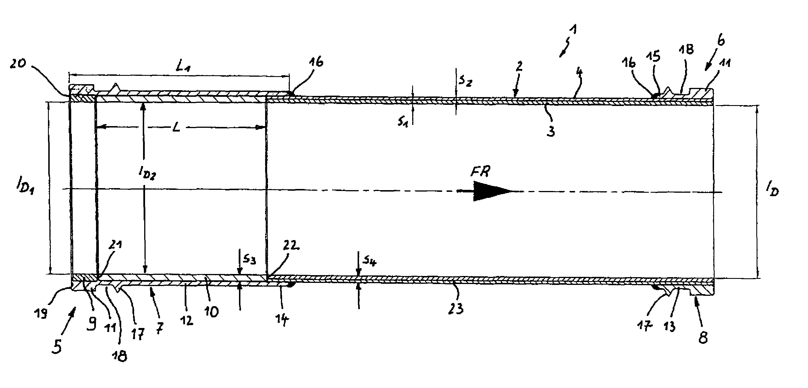
[0009]The delivery pipe includes a pipe body which is equipped on both sides with coupling collars. The coupling collars permit the delivery pipes to be assembled to a pipeline, whereby an exchange of individual delivery pipes of the otherwise closed pipeline is also possible. In the region of the inlet-side coupling collar, a first wear ring and a second wear ring are arranged in succession in the longitudinal direction of the pipe body. The essence of the invention resides in the configuration of the second inner wear ring of a length which is greater than or equal to half the inner diameter of the pipe body. As a result, wear phenomena on the inlet side can be reduced or sufficiently minimized so that the wear in the zone of the second wear ring equals about the wear that occurs in the remaining pipe body, when viewed in the delivery direction. This is accomplished by the second wear ring whose length equals at least half the inner diameter of the pipe body or whose length is greater than that. The use of the delivery pipe in accordance with the invention is tied to the delivery direction. The second wear ring is sized long enough so that turbulences formed on the inlet side as a result of slurry of the transported material advanced at the inner perimeter being sheared off at the transition between two delivery pipes have calmed down again within the zone of the second wear ring. By and large, the average service life of a delivery pipe can thus be significantly increased.
[0013]The inner diameter of the first wear ring is sized smaller than the inner diameter of the second wear ring. The inner diameter of the second wear ring, in turn, is sized smaller than the inner diameter of the pipe body. As a result, when viewed from the inlet side, the inner diameter of the delivery pipe increases starting from the first wear ring via the second wear ring and towards the pipe body so that no protruding edges are present in the delivery direction. This measure supports laminar flow patterns within the pipeline and contributes to wear reduction.
[0017]With respect to the assembly, it is advantageous to provide a circumferential rim at the inner perimeter of the inlet-side coupling collar. This rim serves as a stop for positioning the first wear ring and the second wear ring within the coupling collar. The first wear ring and the second wear ring are each inserted into the coupling collar from opposite open sides of the coupling collar and then come in contact at the rim.
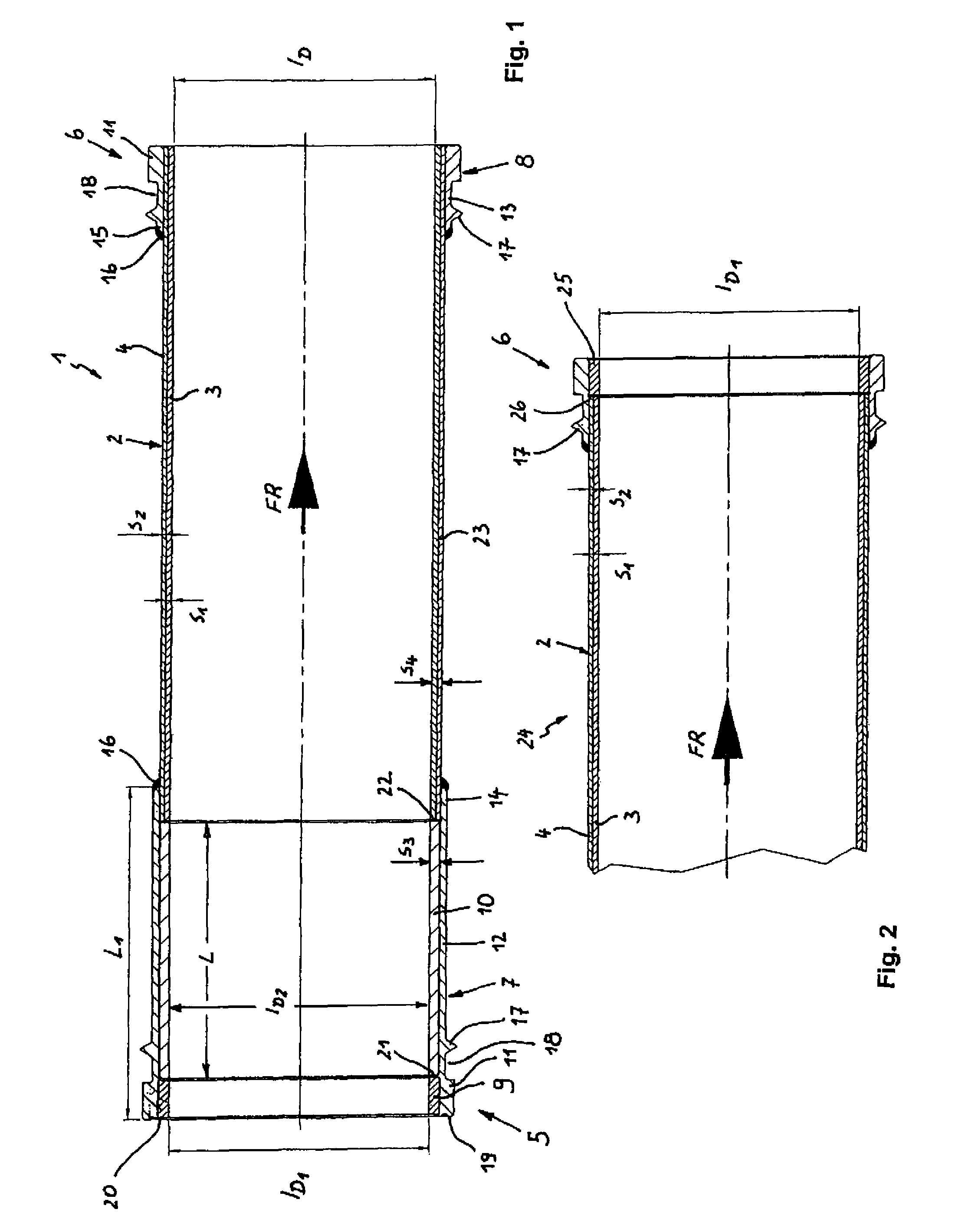
[0019]Using the first wear ring and the long second wear ring on the inlet-side end of the pipe body allows for a significantly improved delivery pipe in terms of its service life. Additionally, a wear ring can also be provided on the outlet-side end of the pipe body in order to counter possible wearing phenomena at the outlet-side end of the delivery pipe. In general, the delivery pipe in accordance with the invention may be provided, however, without a wear ring on the outlet-side end of the pipe body. This contributes to a cost compensation for the added costs that are incurred by the provision of the long second wear ring on the inlet side in accordance with the invention.

Problems solved by technology

Naturally, in operation, the delivery pipes are subject to wear phenomena.
Increased wear is observed in particular on the inlet side of the pipe body of a delivery pipe.
This wear is disproportionately higher than the wear in the remaining area of a delivery pipe.

Method used


Image

  • Delivery pipe for the transport of solids
  • Delivery pipe for the transport of solids

Examples


Embodiment Construction

[0025]Arrow FR designates the delivery direction in each of FIGS. 1 and 2.

[0026]FIG. 1 shows a delivery pipe 1 that has a double-layer pipe body 2 which includes a highly wear-resistant, hardened inner pipe 3 and a pressure-resistant outer pipe 4. The wall thickness of the inner pipe 3 is referenced with s1, the wall thickness of the outer pipe 4 is referenced with s2. It can be seen that the wall thickness s1 of the inner pipe 3 is greater than the wall thickness s2 of the outer pipe 4.

[0027]Coupling collars 7 and 8 are secured on the inlet-side pipe end 5 and the outlet-side pipe end 6, respectively. Received in the inlet-side coupling collar 7 are a first wear ring 9 and a second wear ring 10 arranged in succession in the longitudinal direction of the pipe body 2. The first wearing material 9 is made of wear-resistant and impact-resistant material, such as a ceramic material, a chromium carbide cast, a martensitic nickel-containing wear-resistant cast iron (Ni-hard), or similar w...


PUM


Abstract

A delivery pipe (1) for the transport of solids is described. The delivery pipe (1) has a double-layer pipe body (2) which has a coupling collar (7, 8) on the inlet-side pipe end (5) and on the outlet-side pipe end (6). A first wear ring (9) and a second wear ring (10) are provided in succession in the longitudinal direction of the pipe body (2) in the region of the inlet-side coupling collar (7). The second inner wear ring (10) has a length (L) which is sized greater than or equal to half the internal diameter (ID) of the pipe body (2). As a result, wear phenomena can be reduced in the inlet-side region of the delivery pipe (1) and the service life of the delivery pipe (1) can be increased considerably.

Description

BACKGROUND OF THE INVENTION[0001]The invention relates to a delivery pipe for the transport of solids.[0002]Such a delivery pipe is part of the state of the art as disclosed by, e.g., DE 198 09 529 C2. This delivery pipe has two wear rings arranged in succession in the region of the coupling collar on the inlet side.[0003]Delivery pipes are widely used in the pipeline of concrete-distribution rigs of mobile concrete pumps. Besides the pumping capacity and delivery rate of the pump, important criteria of a mobile concrete pump are the reach height and / or the reaching area of the distributor rig, and here, in turn, a great wear resistance of the pipeline.[0004]Naturally, in operation, the delivery pipes are subject to wear phenomena. Increased wear is observed in particular on the inlet side of the pipe body of a delivery pipe. This wear is disproportionately higher than the wear in the remaining area of a delivery pipe.[0005]In order to reduce the wear on the inlet-side end of the de...

Claims


Application Information

Patent Timeline
Patent Type & Authority Patents(United States)
IPC IPC(8): F16L9/04
CPCF16L57/06B65G53/523E04G21/0418B65G2207/48B65G2207/28
Inventor ESSER, ALEXANDER
Owner ESSER WERKE
Learn More