
Broadcast distributing system and broadcast distributing method

a technology of broadcast distribution and broadcasting, applied in the field of broadcast distribution, can solve the problems of broadcast program delay, inability to guarantee the bandwidth required for data delivery and the time required until data arrives at the terminal, and the drawback of the intern

Inactive Publication Date: 2011-06-21
FUJITSU LTD
View PDF12 Cites 34 Cited by
  • Summary
  • Abstract
  • Description
  • Claims
  • Application Information

AI Technical Summary

Benefits of technology

The present invention provides a solution for improving the distribution of broadcast data over a network. It involves a transmitting apparatus that prioritizes the transfer of each packet of data and sends it into the network based on its own priority. A receiving apparatus then stores the data in a buffer and outputs it periodically to avoid overloading the network. The transmitting apparatus also takes into account the buffer occupancy of the receiving apparatus to determine the priority of each packet. This approach ensures efficient and reliable distribution of broadcast data over a network.

Problems solved by technology

However, due to some reasons if it is difficult to directly receive a broadcast program from a television station, the mobile terminal receives the broadcast program from a base station instead of the television station.
It is economically or due to other reasons difficult to newly establish a transmission medium that can replace the radio-wave-based distribution.
However, the Internet has a drawback that the bandwidth required for data delivery and the time required until arrival of data to a terminal cannot be guaranteed.
In other words, delay can occur when a broadcast program is distributed via the Internet network to two different terminals using the conventional technology.
As a result, it is almost impossible to use the Internet to perform simultaneous broadcasting (simulcasting).
As a result, a huge workload is exerted on the network.

Method used


Image

  • Broadcast distributing system and broadcast distributing method
  • Broadcast distributing system and broadcast distributing method
  • Broadcast distributing system and broadcast distributing method

Examples


Embodiment Construction

[0026]Exemplary embodiments of the present invention will be explained hereinafter with reference to the accompanying drawings.

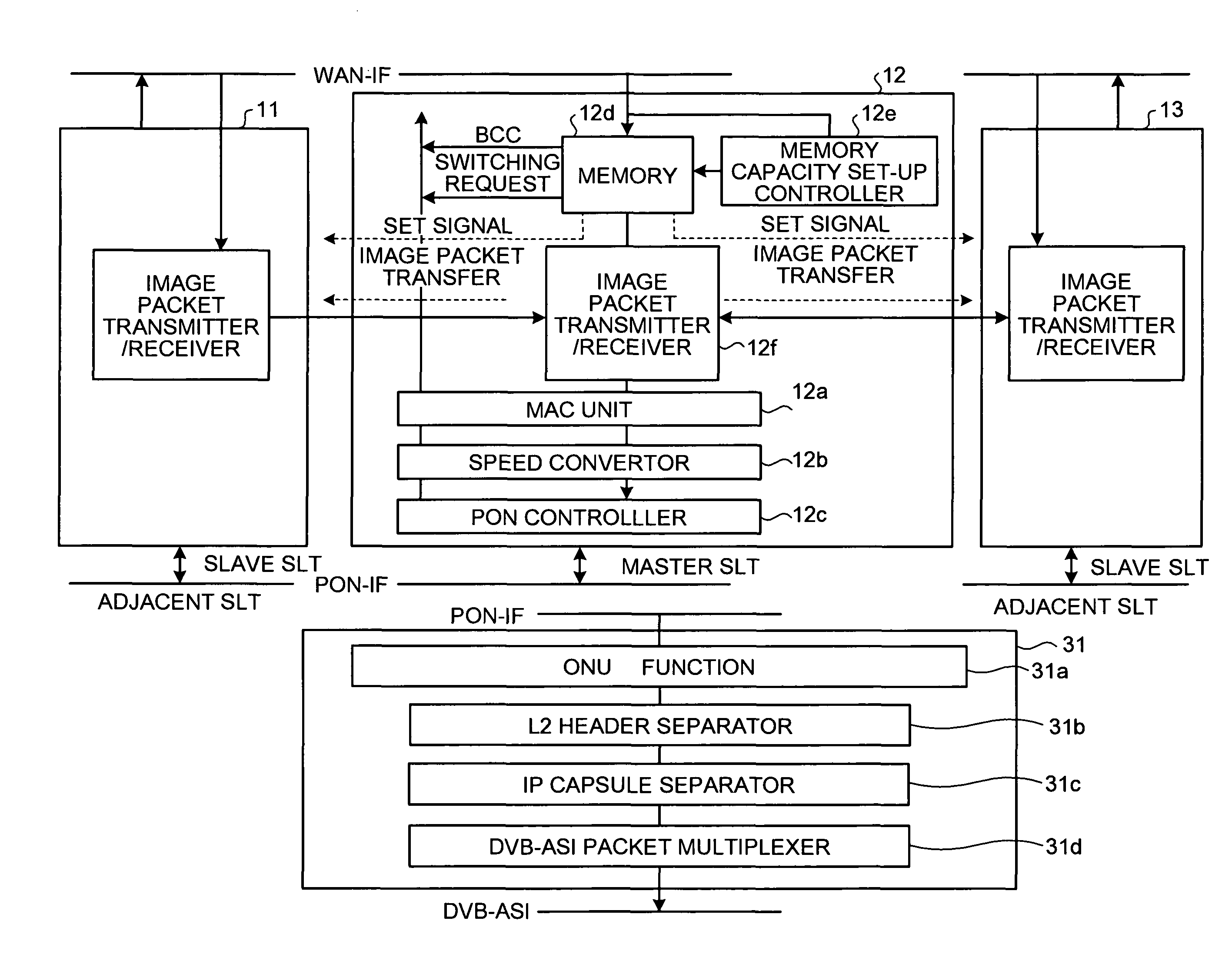
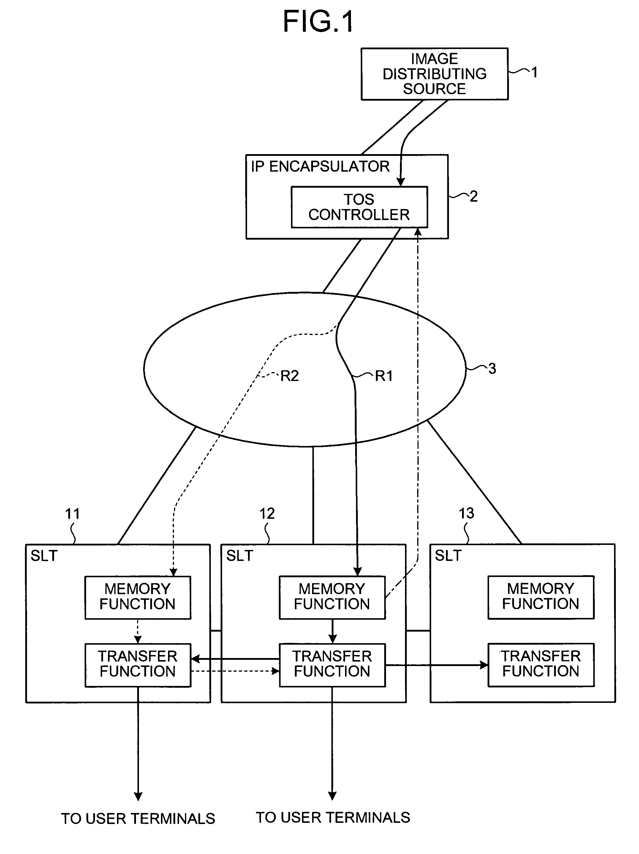
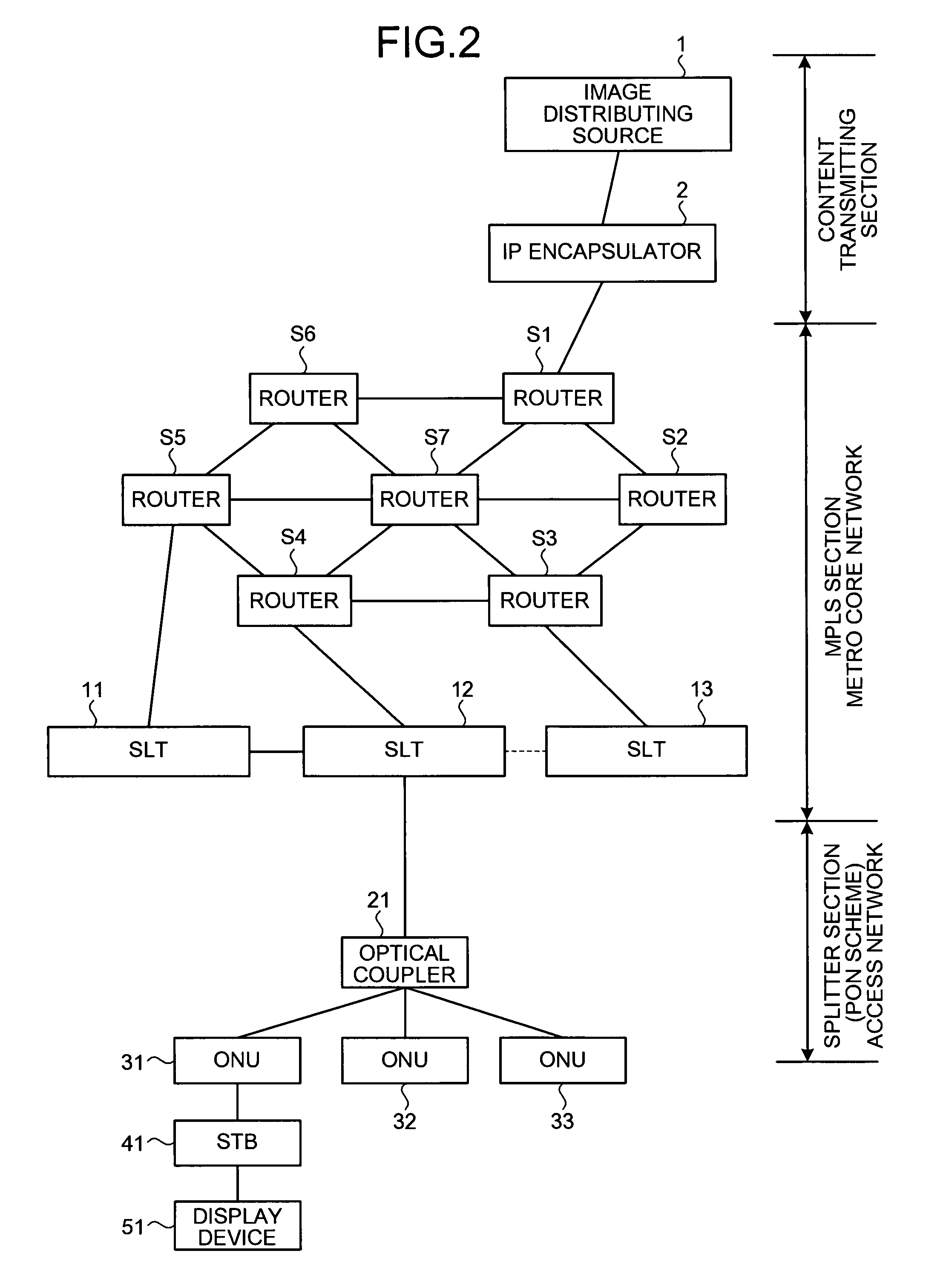
[0027]First, an overview of a broadcast distributing system according to a first embodiment of the present invention will be described with reference to FIG. 1. The broadcast distributing system according to the first embodiment includes an image distributing source 1, an IP encapsulator 2, a network 3, and a plurality of subscriber line terminals (SLTs) 11 to 13. The IP encapsulator 2 IP-encapsulates image data received from the image distributing source 1. The IP encapsulator 2 transmits the IP-encapsulated image data to the subscriber line terminal (SLT) 12 via the network 3.

[0028]The SLT 12 receives the IP-encapsulated image data from the network 3 and temporarily stores the packet data in a memory, and subsequently transmits the image data to each user terminal. The SLT 12 receives, for example, ten channels' worth of television broadcast programs from ...


PUM


Abstract

An IP encapsulator in a broadcast distributing system divides broadcast data received from an image distributing source into packets, and IP-encapsulates the packets. The IP encapsulator transmits the IP-encapsulated packets to a subscriber line terminal (SLT) via a network. The SLT includes a memory that stores therein broadcast data, and performs TOS control and transfer-route switching control based on memory occupancy of the SLT.

Description

BACKGROUND OF THE INVENTION[0001]1. Field of the Invention[0002]The present invention generally relates to a broadcast distribution technique, and particularly relates to broadcast distribution via an Internet protocol (IP) network.[0003]2. Description of the Related Art[0004]Television broadcast programs, radio broadcast programs and the like are typically distributed by radio waves. The advantage of distributing the broadcast programs by radio waves is that users located at different locations can view the same program at the same time.[0005]However, in recent years, with developments in network technology, there is an increasing demand for a broadcasting scheme other than the conventional radio-wave-based distribution.[0006]For example, Japanese Patent Application Laid-open No. 2006-25278 discloses a mobile terminal capable of directly receiving broadcast programs from a television network. However, due to some reasons if it is difficult to directly receive a broadcast program fr...

Claims


Application Information

Patent Timeline
Patent Type & Authority Patents(United States)
IPC IPC(8): H04L12/56H04H60/82H04L47/20
CPCH04H20/82H04L45/00H04L47/30H04L45/50H04L47/10H04L45/22H04H20/40
Inventor SAKATA, TAKASHIIWABUCHI, NOBORUKAWAKAMI, TAKASHI
Owner FUJITSU LTD
Learn More