Portable curb ramp

a curb ramp and portability technology, applied in the direction of inclined ship lifting, hoisting equipment, construction, etc., can solve the problems of increased wear and tear of equipment, increased risk of serious injury for users, and increased risk of damage to equipment, so as to achieve the effect of convenient storage and easy adjustment of the distance between the ramps

Inactive Publication Date: 2011-06-21
HANNAM MICHAEL T
View PDF11 Cites 0 Cited by
  • Summary
  • Abstract
  • Description
  • Claims
  • Application Information

AI Technical Summary

Benefits of technology

[0010]A portable ramp made according to this invention includes a pair of rubber ramps for use with high-centering wheeled lawn equipment. The ramps allow the piece of wheeled lawn equipment to move between a first lower elevation and a second higher elevation without its front wheels becoming airborne as the equipment traverses the ramps in a forward direction.
[0011]The ramps are connected to one another by a flexible tether. The flexible tether allows the distance between the ramps to be easily adjusted and provides a means for stowing the ramps over the handles of the lawnmower. The ramp has a substantially smooth sloping contact surface on a top side that provides for traction yet does not accumulate dirt and debris. The first end of the ramp receives the swivel wheels of the walk-behind as the wheels first make contact with the ramp. The second end of the ramp allows the walk-behind to traverse the curb without high centering. Magnets may be included in a bottom portion of the ramp to secure the ramp to the mower deck.
[0012]An object of the present invention is to provide an inexpensive portable curb ramp that compensates for the high-centering characteristic of walk-behind mowers. Another object of the invention is to provide a curb ramp that may be easily stowed on the equipment without having to rely upon the mower deck. Yet another object of this invention is to provide a pair of curb ramps that may be quickly adjusted to accommodate a different wheel base. A further object of this invention is to provide a ramp with a top surface that does not accumulate dirt, oil and debris yet provides sufficient traction for a walk-behind to traverse the ramp.

Problems solved by technology

Traversing curves causes added wear and tear on the equipment and, in many cases, results in damage to the equipment.
Traversing curves also places the user at risk of serious injury.
Damage and injury are particularly problematic with commercial or large walk-behinds, that is, mowers having mower decks of 30 inches or more.
Because large walk-behinds are high centering as well as heavy, they are difficult to control, especially as the power-driven rear wheels contact the face of the curb and traverse the curb.
The additional weight of the mower combined with the higher handle location makes a standup mower nearly impossible to pop up over a curb.
To solve these problems, some users rely on boards or other ramp-like devices in an attempt to eliminate these problems but boards and similar devices often break slip or slide off of the curb during use, are cumbersome to use, may be set non-parallel to one another or at an improper distance, and are usually not readily accessible when needed because they cannot be stowed on the equipment.
More importantly, none of these devices account for the high centering characteristic of the larger walk-behind mowers.
Because the ramp is designed to go over the top of the curb, the ramp does not account for the high centering characteristic of large walk-behinds.
The ramp also does not allow a user to establish a pre-set distance between the ramps.
Additionally, because the ramp requires ridges to provide the necessary traction, the top surface of the ramp traps dirt, oil and debris that lessen the effectiveness of the ridges over time.
Although this ramp does not extend over the top of the curb, it includes ridges that collect dirt and debris and is designed to be backed over, making it unsafe for use with a walk-behind.
Even if not backed-over, the ramp is not convenient for use with walk-behinds because there is no place on the mower deck to stow such a large ramp.
The ramp is expensive, making it economically unattractive to landscapers and lawn services that own multiple walk-behind mowers.
Although this ramp does not extend over the top of the curb, it can only be stowed on the user's lap while the lawn tractor is in use.
The metal edges of the ramp present an additional safety hazard to users.
The threaded rod makes the ramp inconvenient for use with walk-behind mowers (there is no “lap” to store it on”) and precludes quick changeover to a different between-ramp distance.

Method used


Image

  • Portable curb ramp
  • Portable curb ramp
  • Portable curb ramp

Examples


Embodiment Construction

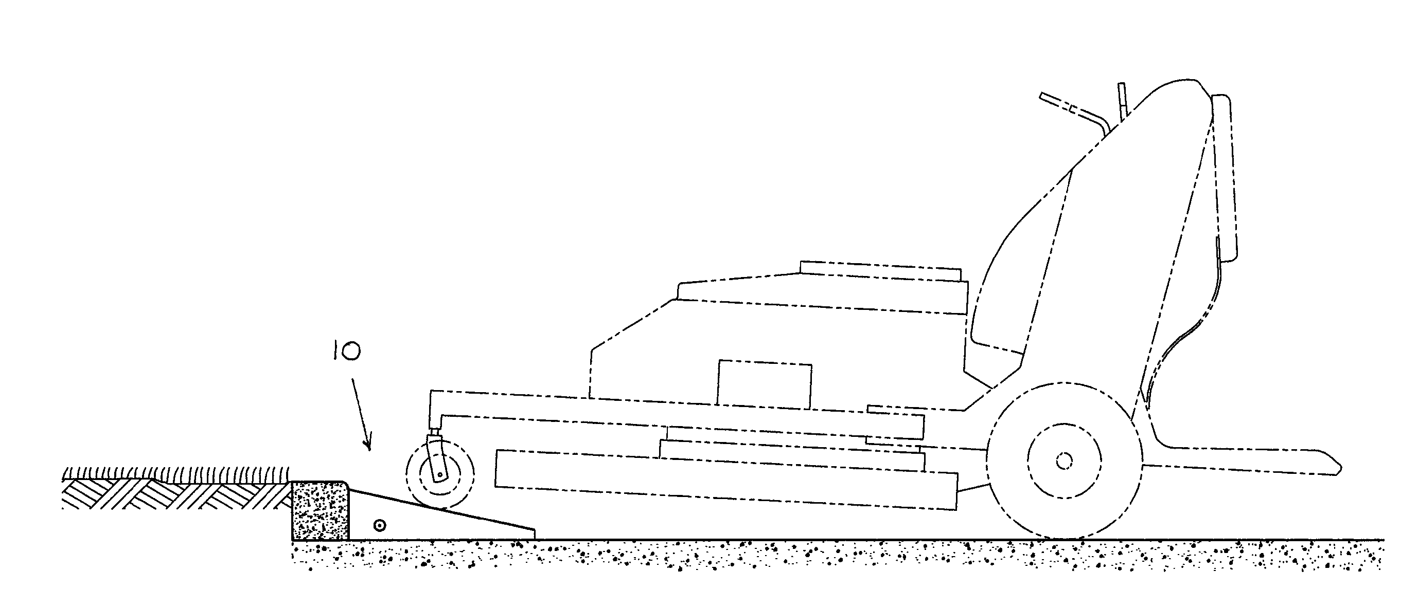
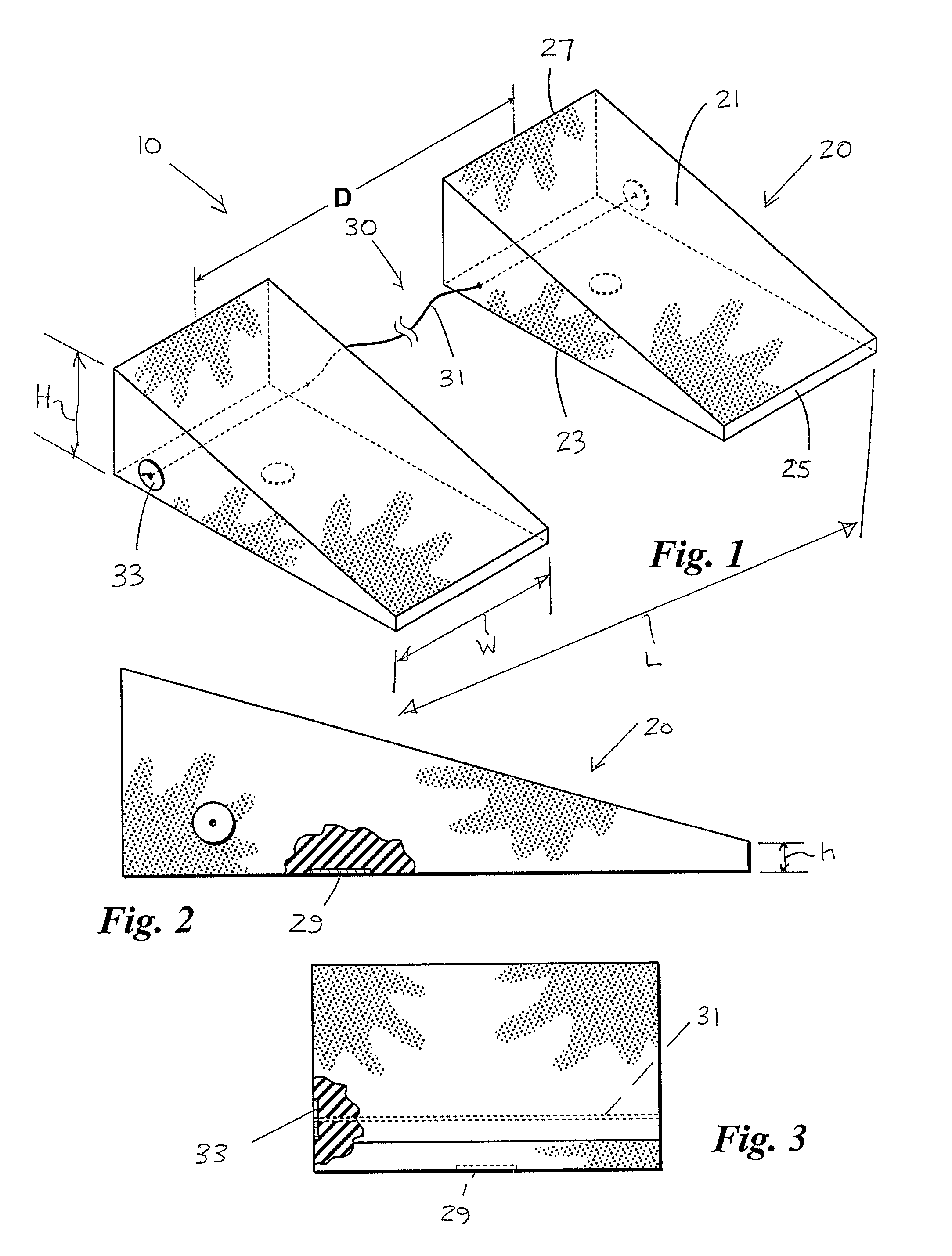
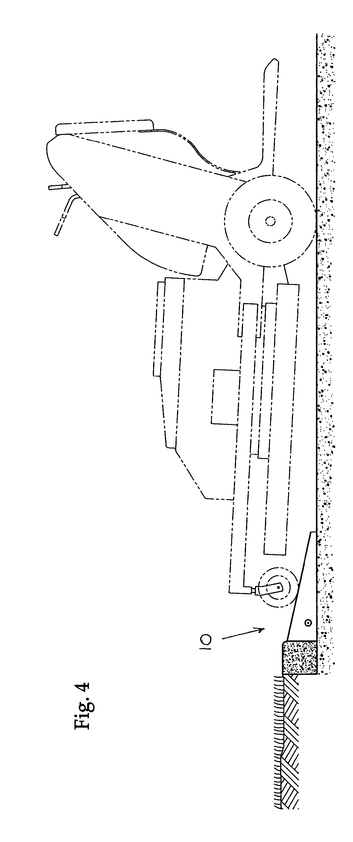
[0017]Referring first to FIG. 1, a portable ramp 10 is illustrated that includes a pair of rubber ramps 20 that are connected to one another by a flexible tether 30. Each ramp 20 has a sloping contact surface 21 on its top side, a planar contact surface 23 on its bottom side, and two opposing and substantially parallel ends 25 and 27. Sloping contact surface 21 is preferably a substantially smooth surface having a slope of about 20°. Planar contact surface 23 may include a magnet 29 located residing within an interior portion of the ramp 20. End 25 has sufficient height to receive yet partially slow an oncoming piece of wheeled lawn equipment. About ½-inch height “h” has been found to be effective for this purpose. The shape of end 25 also provides for improved resistance to wear-and-tear caused by wheeled lawn equipment as the wheels of that equipment come into contact with ramp 10. End 27 serves to compensate for the high centering of walk-behind wheeled lawn equipment by exposing...


PUM


Abstract

A portable ramp made according to this invention includes a pair of interconnected ramps for use with high-centering wheeled lawn equipment such as commercial walk-behind mowers. The ramps allow the equipment to move between a first lower elevation and a second higher elevation without its front wheels becoming airborne as the equipment traverses the ramps in a forward direction. The ramps are connected to one another by a flexible tether that allows the distance between the ramps to be easily adjusted and provides a means for stowing the ramps over the handles of the equipment Magnets may be included in a bottom portion of the ramp to provide an optional means for stowing the ramps on the equipment.

Description

BACKGROUND OF THE INVENTION[0001]This invention relates to portable ramps and more particularly, portable ramps that allow high centering wheeled lawn equipment, such as commercial walk-behind lawnmowers, to safely and easily traverse over curbs.[0002]Wheeled lawn care equipment, such as commercial walk-behind mowers (“walk-behinds”), zero-turning radius riding mowers and tractors, must sometimes traverse over curbs and other obstructions in order to get to grass cutting and work areas. Traversing curves causes added wear and tear on the equipment and, in many cases, results in damage to the equipment. Traversing curves also places the user at risk of serious injury. Damage and injury are particularly problematic with commercial or large walk-behinds, that is, mowers having mower decks of 30 inches or more. These mowers tend to be “high centering” because the lighter mower deck sits forward of the engine that propels the mower forward and drives the cutting blades. Other types of wh...

Claims


Application Information

Patent Timeline
IPC IPC(8): B66F19/00
CPCB66F7/243
Inventor HANNAM, MICHAEL T.
Owner HANNAM MICHAEL T
Why Eureka
Try Eureka