Measuring apparatus, measuring method, and sound signal processing apparatus
a technology of measuring apparatus and measuring method, which is applied in the direction of electrical apparatus, stereophonic systems, stereophonic arrangments, etc., can solve the problems of limited measurable delay time length and the inability to measure the delay time related to the relatively long distance between the speaker and the microphone, so as to achieve long delay time, measure long delay time, and simple operation
- Summary
- Abstract
- Description
- Claims
- Application Information
AI Technical Summary
Benefits of technology
Problems solved by technology
Method used
Image
Examples
first embodiment
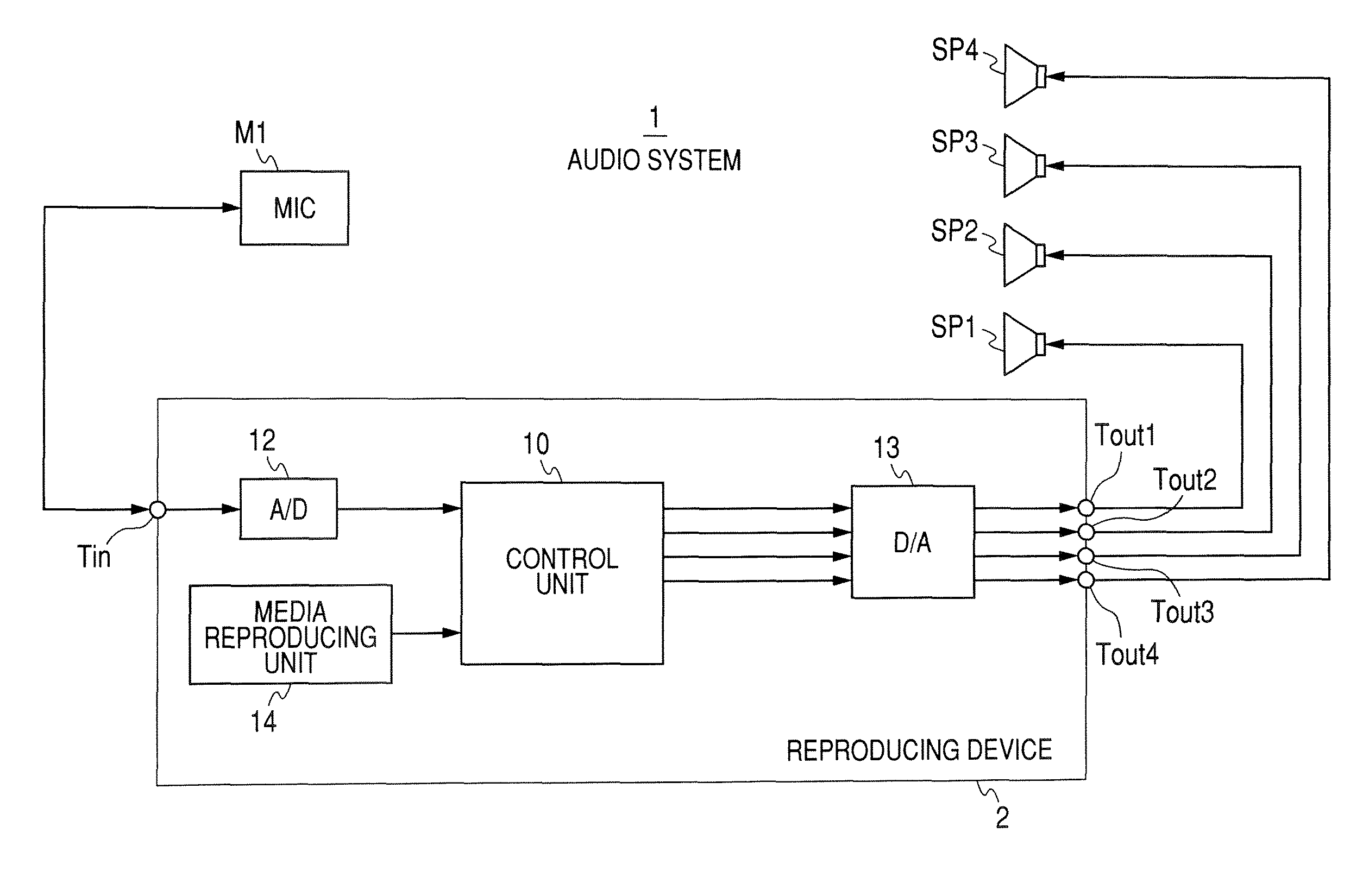
[0082]FIG. 3 is a view schematically explaining an operation of measuring delay time according to a first embodiment. Here, in the following description, only an operation of measuring delay time with respect to one speaker SP will be described for the convenience of explanation. However, in order to measure delay time with respect to the respective speakers SP, the same measuring operation may be repeatedly performed for the respective speakers SP.
[0083]First, in the first embodiment, an A signal (first sine wave signal) having a frequency of 320 Hz and a B signal (second sine wave signal) having a frequency of 300 Hz are set as sine wave signals having different frequencies. In addition, the A and B signals are sequentially output from the speaker SP, and collected signals corresponding to the sequentially output A and B signals are sequentially input.
[0084]That is, in this case, as shown by 1> in FIG. 3, for example, the A signal is output from the speaker SP. Then, a signal, whi...
second embodiment
[0127]FIG. 9 is a view schematically illustrating an operation of measuring delay time according to a second embodiment.
[0128]In the second embodiment, A and B signals are set to be output at the same time, as compared with the first embodiment in which the A and B signals are separately output.
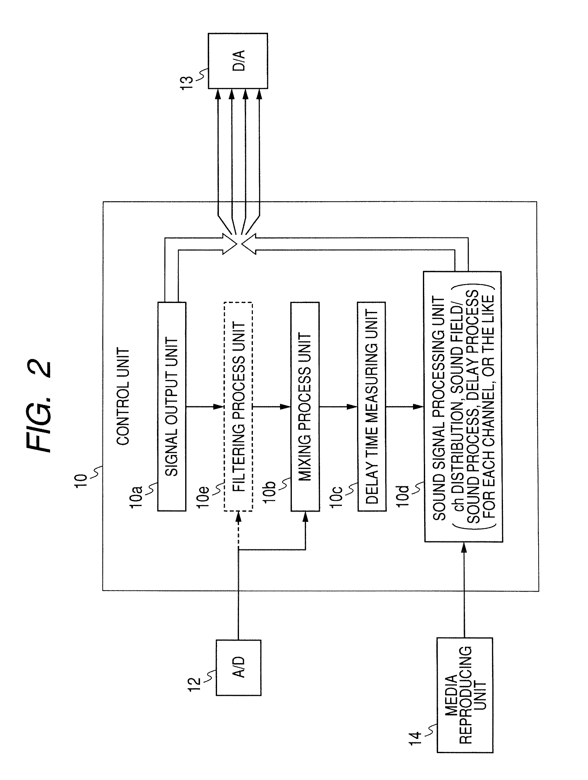
[0129]Here, in order to perform a mixing process, these A and B signals need to be acquired as separate signals. Therefore, in the second embodiment, a band pass filter, which is provided to separately output the A and B signals that are output at the same time such that the A and B signals can be acquired as separate signals, is needed. That is, in this case, the control unit 10 includes the filtering process unit 10e described above.
[0130]Hereinafter, the operation according to the second embodiment will be specifically described. First, as shown by 1> in FIG. 9, the A and B signals are output at the same time. For example, the simultaneous output is made by outputting a signal, which is ge...
third embodiment
[0142]A third embodiment is an application of the second embodiment. In the third embodiment, sine wave signals having different frequencies are simultaneously output from a plurality of speakers SP. Even in the third embodiment, the control unit 10 includes the filtering process unit 10e that is provided to extract sine wave signals included in a collected signal.
[0143]For example, in the third embodiment, a case is exemplified in which sine wave signals are simultaneously output from all of the speakers SP. Specifically, in this case, an A1 signal (320 Hz) and a B1 signal (300 Hz) are output from the speaker SP1, an A2 signal (360 Hz) and a B2 signal (340 Hz) are output from the speaker SP2, an A3 signal (400 Hz) and a B3 signal (380 Hz) are output from the speaker SP3, and an A4 signal (440 Hz) and a B4 signal (420 Hz) are output from the speaker SP4.
[0144]At this time, a frequency of each of the signals is selected such that signals having the same frequency are not included in ...
PUM
 Abstract
Description
Claims
Application Information
 - R&D
- Intellectual Property
- Life Sciences
- Materials
- Tech Scout
- Unparalleled Data Quality
- Higher Quality Content
- 60% Fewer Hallucinations
Browse by: Latest US Patents, China's latest patents, Technical Efficacy Thesaurus, Application Domain, Technology Topic, Popular Technical Reports.
© 2025 PatSnap. All rights reserved.Legal|Privacy policy|Modern Slavery Act Transparency Statement|Sitemap|About US| Contact US: help@patsnap.com


