
RF power amplifier integrated circuit and unit cell

a power amplifier and integrated circuit technology, applied in the field of electronic integrated circuits, can solve the problems of large gate resistance per unit gate width, affecting the battery life and cost of the cell phone, and affecting the performance of the transistor

Active Publication Date: 2011-06-14
PSEMI CORP
View PDF6 Cites 39 Cited by
  • Summary
  • Abstract
  • Description
  • Claims
  • Application Information

AI Technical Summary

Benefits of technology

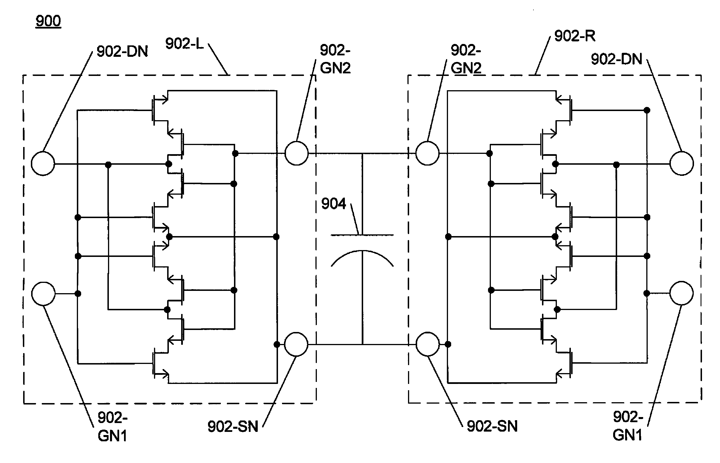
The present patent describes a novel RF power amplifier (PA) integrated circuit (IC) that includes at least two linear arrays of transistor device units and capacitors. The transistor device units include source nodes jointly coupled to a source bus and selected gate nodes jointly coupled to a gate bus. The capacitors are also jointly coupled to the source and gate buses. The capacitors may include various types such as metal-insulator-metal (MIM) capacitors, metal-oxide-semiconductor (MOS) capacitors, vertical native capacitors (VNCAPs), or a combination thereof. The transistor device units may include interdigitated transistors. The PA IC may be implemented using high-resistivity or silicon-on-insulator substrates. The technical effects of this invention include improved RF signal amplification and reduced interference between components.

Problems solved by technology

However, unless the PA power efficiency is also increased, such designs may negatively impact battery life and cost of the cell phone.
This causes a large gate resistance per unit gate width.
Typically, when a single RF transistor's gate width exceeds a few tens of micrometers, or the ratio Wg / Lg is >10, the gate resistance begins to degrade the performance of the transistor.

Method used


Image

  • RF power amplifier integrated circuit and unit cell
  • RF power amplifier integrated circuit and unit cell
  • RF power amplifier integrated circuit and unit cell

Examples


Embodiment Construction

Throughout this description, embodiments and variations are described for the purpose of illustrating uses and implementations of the inventive concept. The illustrative description should be understood as presenting examples of the inventive concept, rather than as limiting the scope of the concept as disclosed herein.

A novel RF power amplifier (PA) integrated circuit (IC), unit cell, and method for amplifying RF signals are described. In accordance with the present disclosure, embodiments of transistor device units are described. Embodiments for improved unit cells are described. Improved PA ICs incorporating the improved unit cells are described. Embodiments for improved bus layouts are described. Embodiments for disposing contact pads in PA ICs are described. Exemplary materials and methods of fabrication are also described.

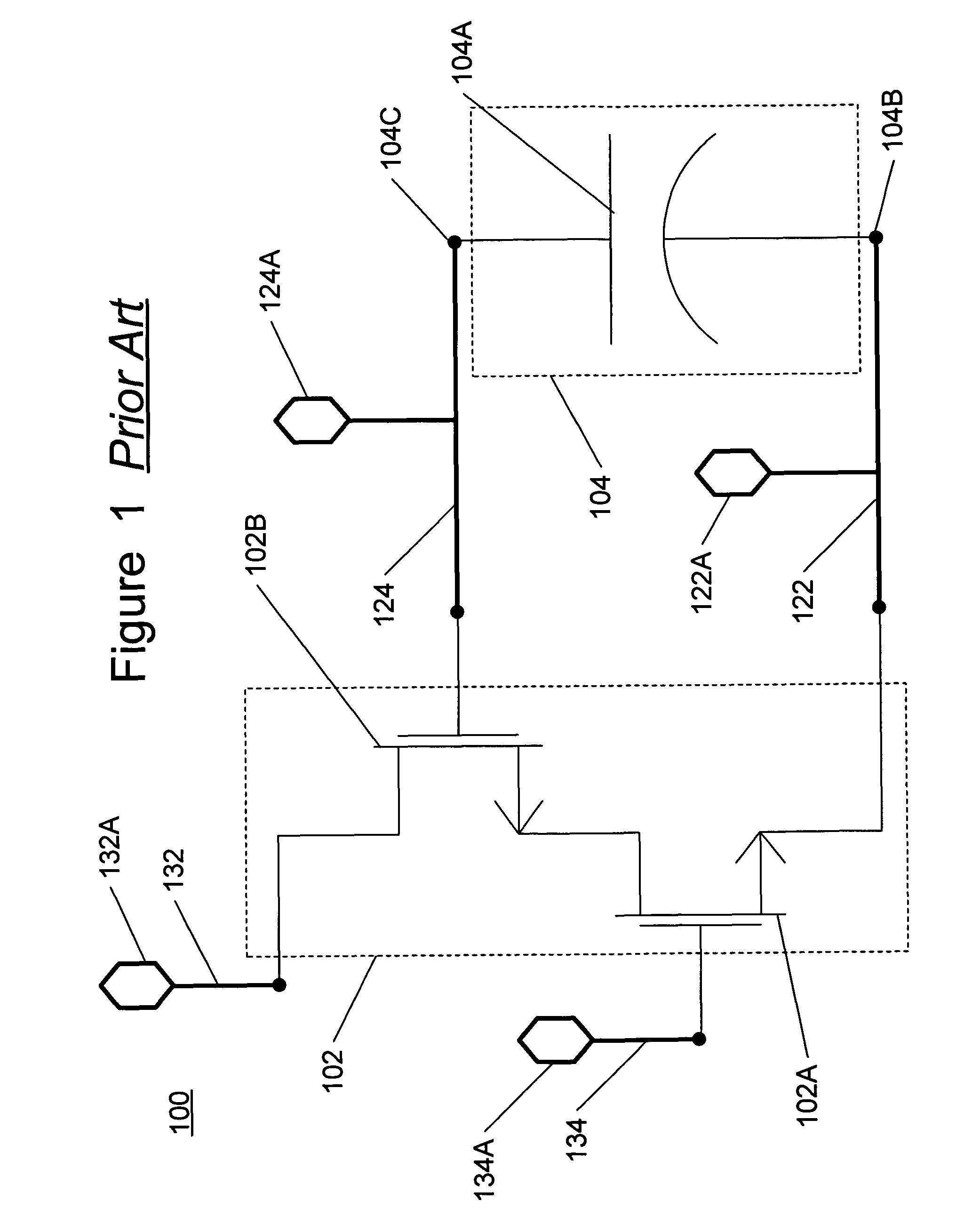
FIG. 1 is a simplified schematic diagram of a PA 100. The schematic of the PA 100 shows a cascode amplifier circuit. Cascode amplifier circuits are well know...


PUM


Abstract

A novel RF power amplifier integrated circuit (PA IC), unit cell, and method for amplifying RF signals are disclosed. One embodiment of a PA IC includes at least two linear arrays comprising transistor device units, and at least one linear array comprising capacitors. The transistor device units include source nodes that are jointly coupled to a source bus, and selected gate nodes that are jointly coupled to a gate bus. First electrodes of the capacitors are also jointly coupled to the source bus, and second electrodes of the capacitors are jointly coupled to the gate bus. Each linear array comprising capacitors is disposed between at least two linear arrays comprising transistor device units. In one embodiment, the PA IC includes unit cells. In some embodiments, each unit cell comprises two transistor device units and one or more capacitors. The capacitors are disposed between the transistor device units. The unit cells are disposed in linear arrays so that the transistor device units are disposed in linear arrays and the capacitors are disposed in linear arrays.

Description

BACKGROUND1. FieldThe present disclosure relates to electronic integrated circuits (“ICs”), and more specifically to RF power amplifiers (“PAs”).2. Description of Related ArtMost radio transceivers, such as cell phones that are a ubiquitous feature of modern life, require an RF PA circuit to boost the transmit signal to a level sufficient to be received by a target transceiver, such as a cellular base station. The performance of the RF power amplifier strongly impacts cell phone features such as battery life, operational range and signal quality. Designs that increase signal quality and transmit power generally increase operational range. However, unless the PA power efficiency is also increased, such designs may negatively impact battery life and cost of the cell phone.Increases in PA power efficiency generally enable improvements in battery life for a selected level of signal quality and operational range. Because removing waste heat incurs costs, improved efficiency generally red...

Claims


Application Information

Patent Timeline
Patent Type & Authority Patents(United States)
IPC IPC(8): H03F3/14
CPCH03F3/195H01L27/0207
Inventor BACON, PETERBROUGHTON, ROBERTLI, YANGBONKOWSKI, JAMESCALANCA, NEIL
Owner PSEMI CORP
Learn More