
Image sensor and method of manufacturing the same

a technology of image sensor and manufacturing method, which is applied in the field of image sensor, can solve the problems of image lag and difference in fermi level, and achieve the effect of reducing image lag

Inactive Publication Date: 2011-06-07
SAMSUNG ELECTRONICS CO LTD
View PDF12 Cites 8 Cited by
  • Summary
  • Abstract
  • Description
  • Claims
  • Application Information

AI Technical Summary

Benefits of technology

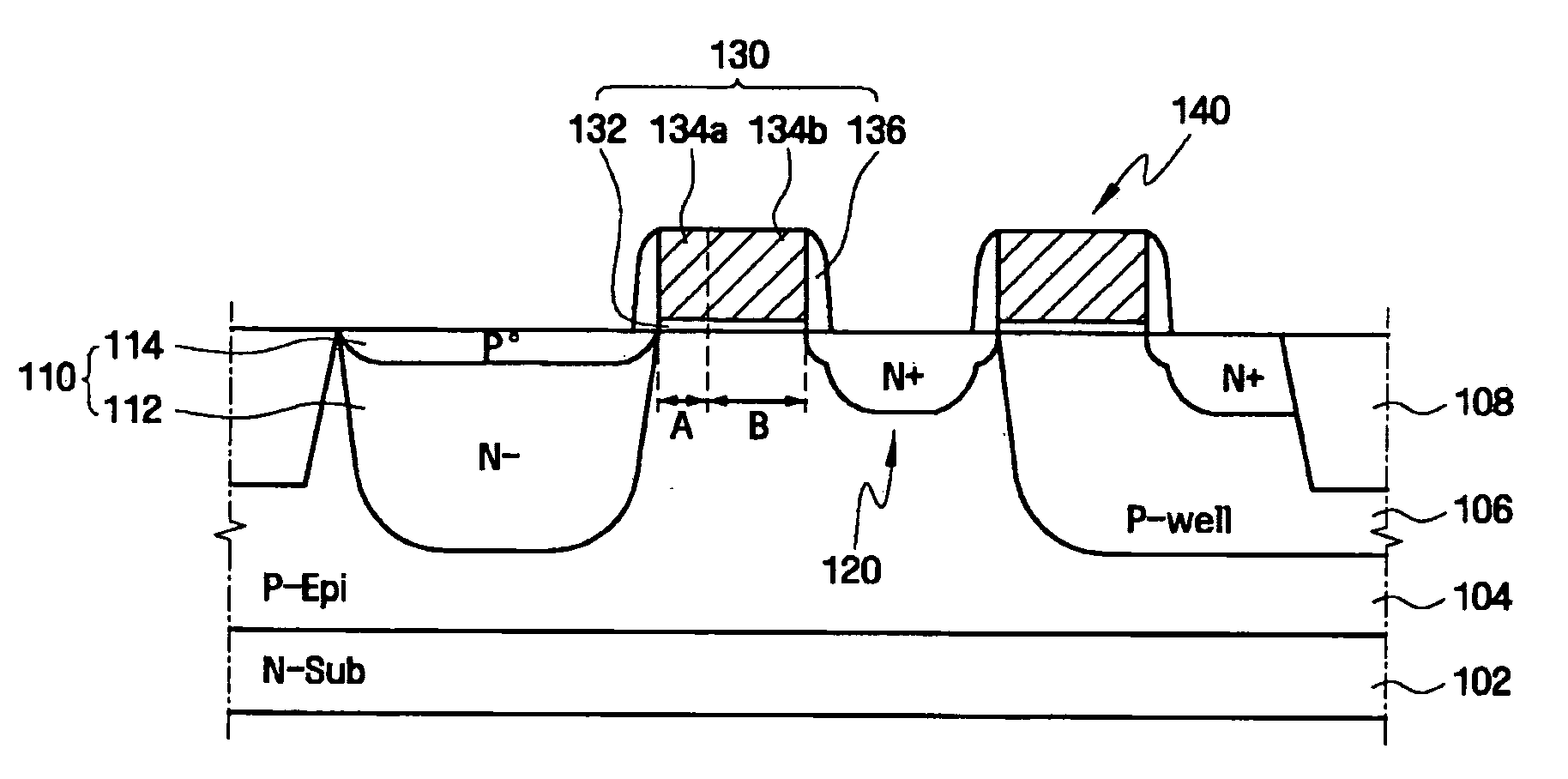
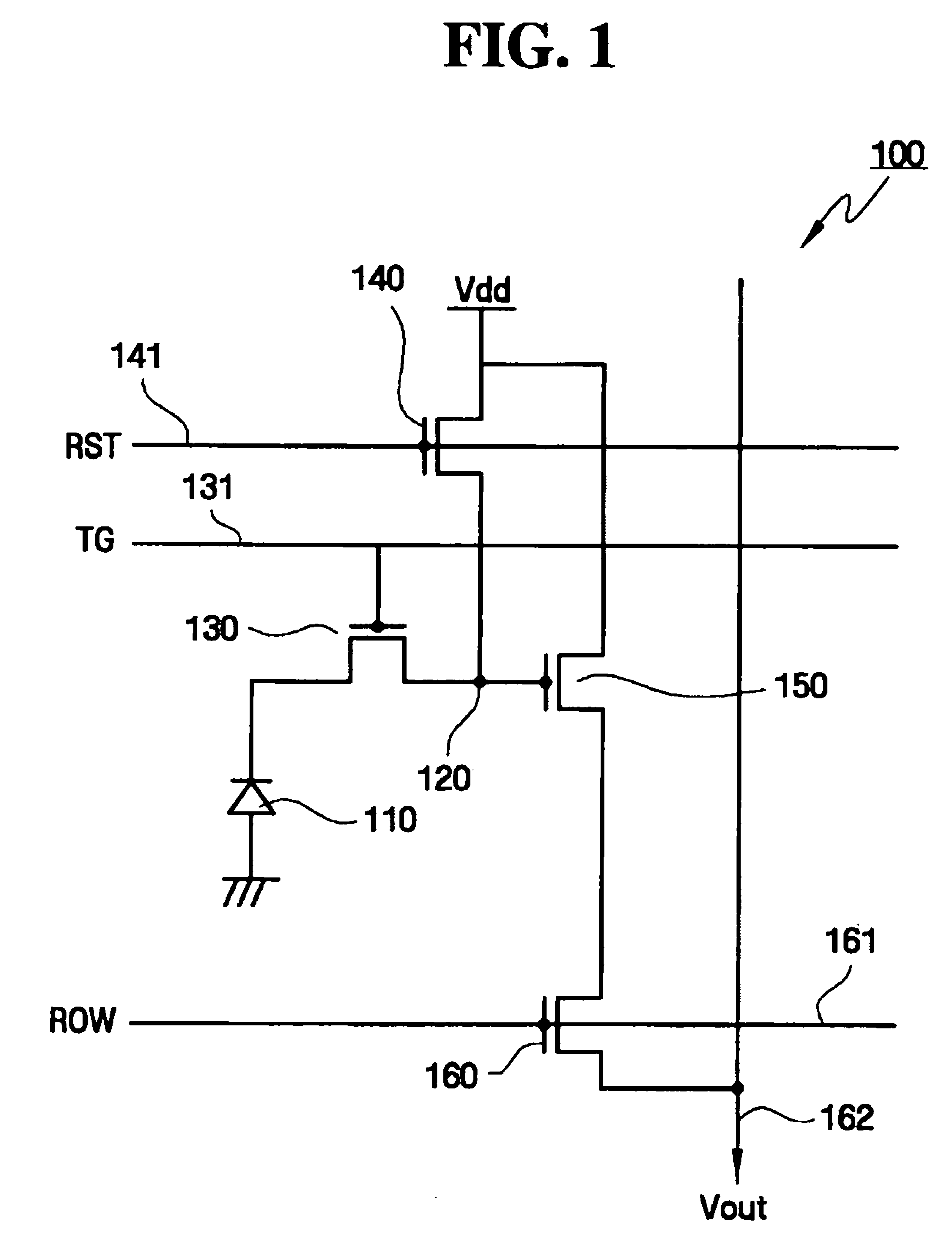
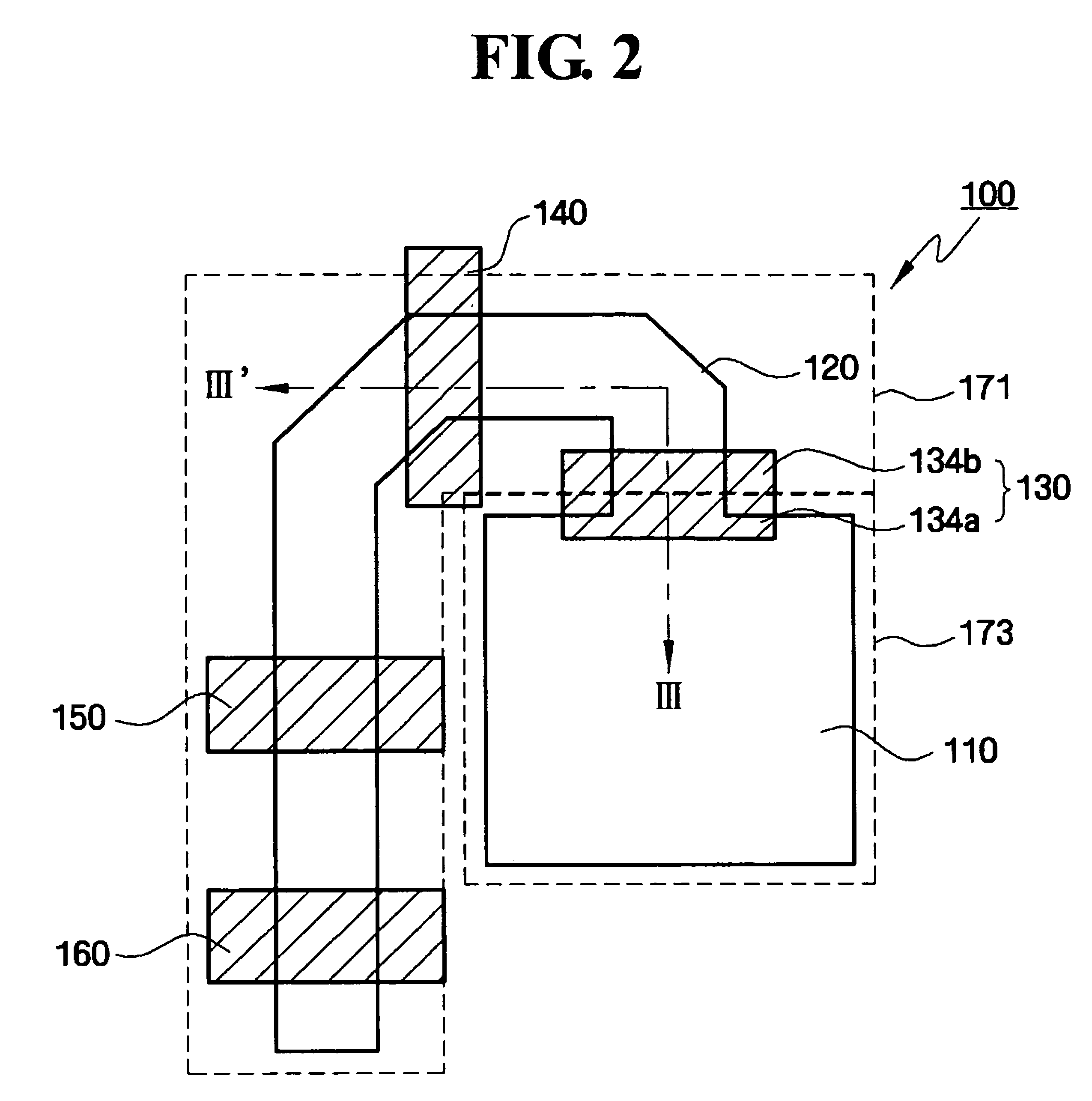
[0011]Example embodiments provide an image sensor capable of reducing image lag.
[0012]Example embodiments also provide a method of manufacturing an image sensor capable of reducing image lag.

Problems solved by technology

These varying concentrations may cause Fermi level difference.
Thus the photocharge may not be completely transferred from the photodiode to the floating diffusion region, resulting in image lag.

Method used


Image

  • Image sensor and method of manufacturing the same
  • Image sensor and method of manufacturing the same
  • Image sensor and method of manufacturing the same

Examples


Embodiment Construction

[0024]Various example embodiments will now be described more fully with reference to the accompanying drawings in which some example embodiments are shown. In the drawings, the thicknesses of layers and regions are exaggerated for clarity.

[0025]Detailed example embodiments are disclosed herein. However, specific structural and / or functional details disclosed herein are merely representative for purposes of describing example embodiments. This disclosure may, however, may be embodied in many alternate forms and should not be construed as limited to only example embodiments set forth herein.

[0026]Accordingly, while example embodiments are capable of various modifications and alternative forms, example embodiments thereof are shown by way of example in the drawings and will herein be described in detail. It should be understood, however, that there is no intent to limit example embodiments to the particular forms disclosed, but on the contrary, example embodiments are to cover all modi...


PUM


Abstract

Example embodiments disclose an image sensor capable of preventing or reducing image lag and a method of manufacturing the same. Example methods may include forming a gate insulating film and a gate conductive film doped with a first-conductive-type dopant on a semiconductor substrate; forming a transfer gate pattern by patterning the gate insulating film and the gate conductive film; and fabricating a transfer gate electrode by forming a first-conductive-type photodiode in the semiconductor substrate adjacent to one region of the transfer gate pattern, by forming a second-conductive-type photodiode on the first-conductive-type photodiode, and by forming a first-conductive-type floating diffusion region in the semiconductor substrate adjacent to the other region of the transfer gate pattern.

Description

PRIORITY STATEMENT[0001]This application claims priority from Korean Patent Application No. 10-2006-0003604 filed on Jan. 12, 2006 in the Korean Intellectual Property Office, the disclosure of which is incorporated herein by reference in its entirety.BACKGROUND[0002]1. Field[0003]Example embodiments described herein relate to an image sensor and a method of manufacturing the same, and, for example, to an image sensor capable of reducing image lag and a method of manufacturing the same.[0004]2. Description of the Related Art[0005]In general, image sensors are semiconductor elements that convert an optical image into an electrical signal. Image sensors can be divided into CCDs (charge coupled devices) and CMOS image sensors.[0006]A CCD is an element in which MOS capacitors may be packed closely and accumulate or transfer charge carriers. A CMOS image sensor may be made to have the same number of MOS transistors as pixels by a CMOS technique using a control circuit and a signal process...

Claims


Application Information

Patent Timeline
Patent Type & Authority Patents(United States)
IPC IPC(8): H01L21/8238
CPCH01L27/14603H01L27/14689H01L27/14609F16C33/7889F16C33/783F16C19/26F16C33/6681
Inventor SONG, JAE-HOPARK, CHANPARK, YOUNG-HOONJUNG, SANG-ILHONG, JONG-WOOKPARK, KEO-SUNGKIM, EUN-SOOPARK, WON-JEPARK, JIN-HYEONGSEONG, DAE-CHEOLLEE, WON-JEONGKIM, PU-RA
Owner SAMSUNG ELECTRONICS CO LTD
Learn More