
Method and system for reducing unburned fuel and oil from exhaust manifolds

a technology of exhaust manifolds and exhaust manifolds, which is applied in the direction of lubrication of crankcase compression engines, electric control, instruments, etc., can solve the problems of unburned fuel and oil accumulation, unwanted delay in operation, and accumulation of unburned fuel and oil

Active Publication Date: 2011-05-31
GE GLOBAL SOURCING LLC
View PDF10 Cites 5 Cited by
  • Summary
  • Abstract
  • Description
  • Claims
  • Application Information

AI Technical Summary

Benefits of technology

[0006]Another embodiment uses a method for operating an internal combustion engine with a plurality of cylinders, the cylinders operating in at least two modes, a first mode with a lower fuel injection amount, and a second mode with a higher fuel injection amount. The method comprises operating at least one of the cylinders of the engine in the second mode while at least another cylinder operates in the first mode to increase exhaust temperature of the at least one cylinder in the second mode after a designated amount of low-load engine operation, and during low-load engine operation. In this way, unburned fuel and / oil accumulating in an engine exhaust system may be removed with reduced need for manual intervention, thereby reducing related costs.

Problems solved by technology

In particular, unburned fuel from combustion during low load conditions can contribute to the accumulation and deposition of unburned fuel and oil in the exhaust system, especially during reduced exhaust port temperatures.
However, the need for frequent exhaust system maintenance compounded with the use of complicated manual maneuvers therein may thereby introduce unwanted delays in the operation.

Method used


Image

  • Method and system for reducing unburned fuel and oil from exhaust manifolds
  • Method and system for reducing unburned fuel and oil from exhaust manifolds
  • Method and system for reducing unburned fuel and oil from exhaust manifolds

Examples


Embodiment Construction

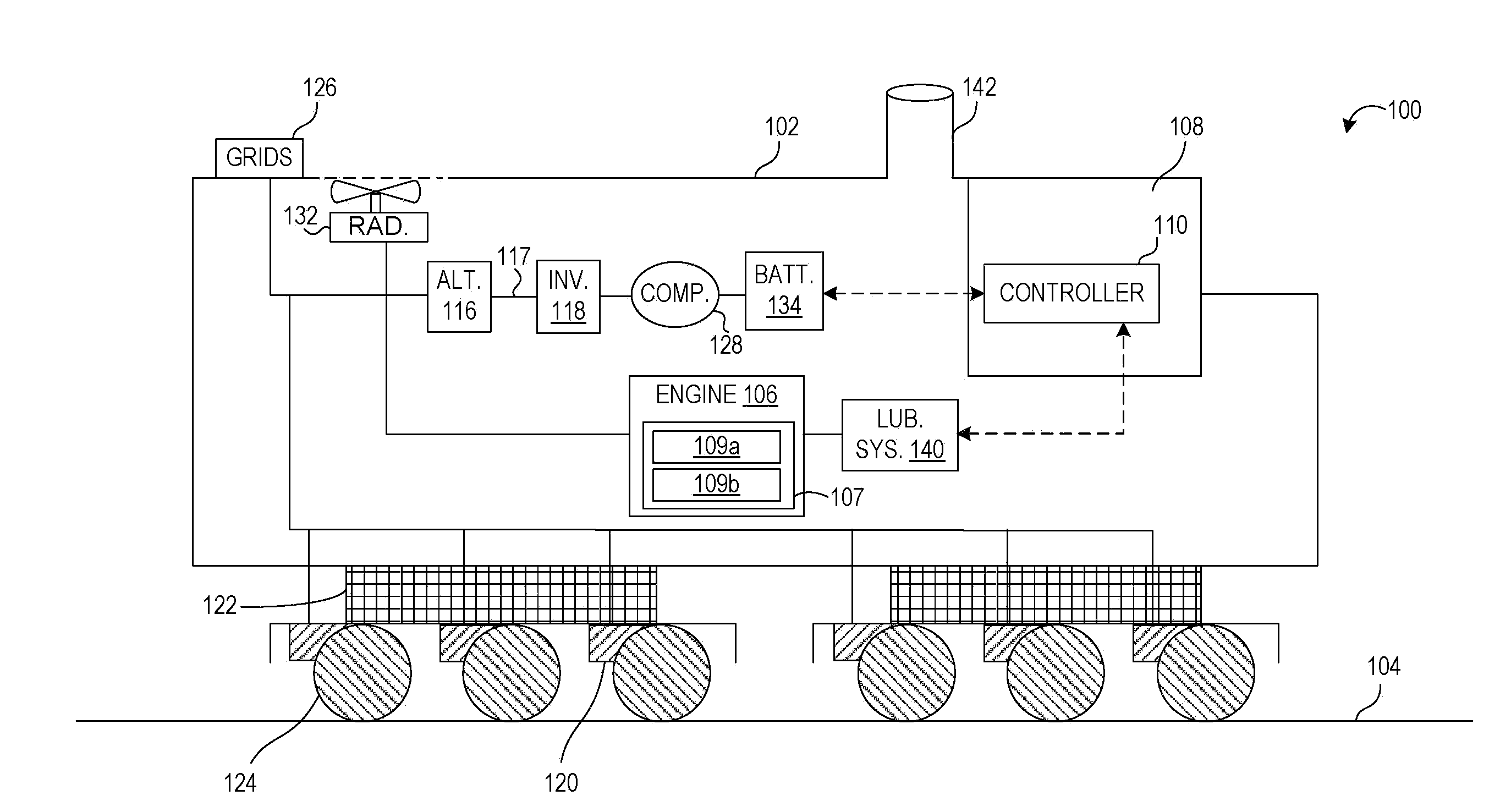
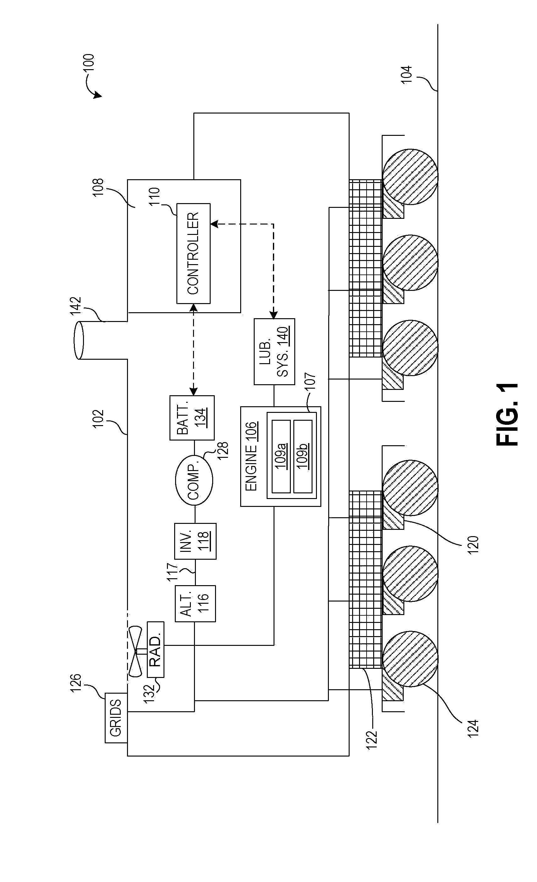
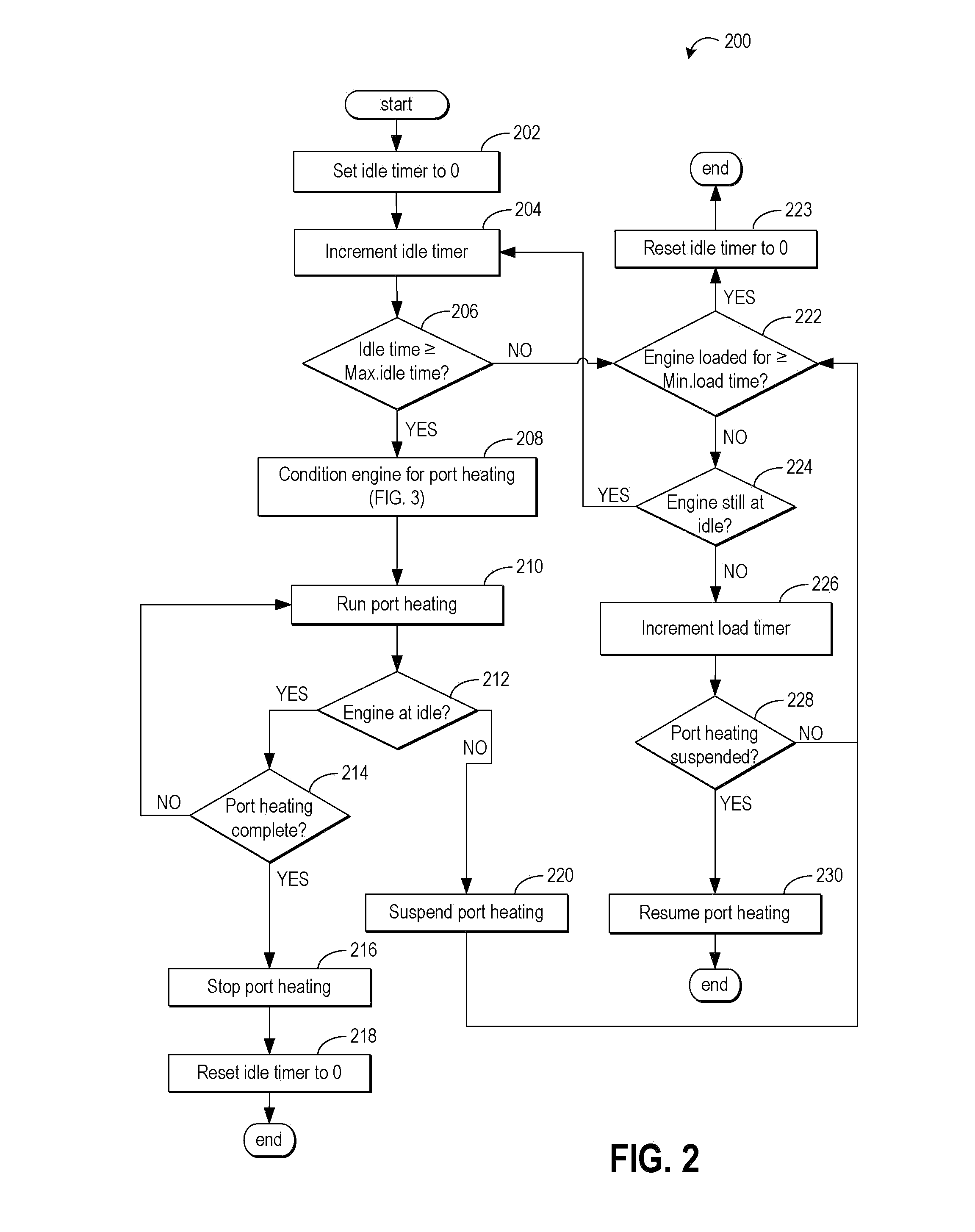
[0013]Engine of locomotives, or other vehicles such as ships, may be configured with lubrication systems that provide oil for lubricating valvetrains, pistons and other related engine components. The lubricating system may be further configured to interact with an engine controlled by an engine control system to enable unburned oil and / or fuel that may have accumulated in the engine exhaust manifold during the course of engine operation to be burned in order to reduce fouling the engine's exhaust system. One example of such a configuration is illustrated with reference to FIG. 1 wherein a lubricating system interacts with a locomotive engine to provide lubrication during engine operation, where an engine controller enables regular exhaust maintenance. As further elaborated in FIGS. 2-3, control routines may be performed to determine if an engine has idled (or operated at low-load) for enough time to warrant a pre-emptive exhaust maintenance procedure. If so, further based on the eng...


PUM


Abstract

Methods and systems are provided for operating an internal combustion engine having an exhaust system and a plurality of cylinders that utilize fuel and / or oil for combustion and engine lubrication purposes. In one example, a method comprises, while the engine is operating in a low-load mode or an idle mode, successively operating distinct subsets of said cylinders at a cylinder load sufficient to increase an exhaust temperature for burning unburned fuel and / or oil deposited in the cylinders or engine exhaust system. Herein, each successively operated subset comprises at least one but fewer than all of the plurality of cylinders, and the cylinders that are not currently being operated in a subset are operated in a low- or no-fuel mode.

Description

FIELD[0001]The subject matter disclosed herein relates to internal combustion engines and, more particularly, to methods and systems for controlling internal combustion engines.BACKGROUND[0002]Locomotives or other vehicles, such as ships, may be configured with lubrication systems wherein pressurized oil is used to lubricate and / or cool engine valvetrain components, camshaft assemblies, pistons, and related engine components. Such oil systems may be configured to supply sufficient oil for engine operation at full load.[0003]In some engines, such as large bore engines designed for significant operation under full load, oil from the lubrication system may be retained in the grooves of a cylinder wall and can eventually enter an exhaust system or engine stack. In particular, unburned fuel from combustion during low load conditions can contribute to the accumulation and deposition of unburned fuel and oil in the exhaust system, especially during reduced exhaust port temperatures.[0004]O...

Claims


Application Information

Patent Timeline
Patent Type & Authority Patents(United States)
IPC IPC(8): F02D41/00G06F19/00
CPCF02D41/008F02N11/0803F02D41/08F02D41/0087
Inventor ROTH, JOHN STEPHENSTOTT, KYLE CRAIGMISCHLER, JAMES ROBERTFLYNN, PAULHEYWOOD, KIRKMOSER, DANIEL ALLAN
Owner GE GLOBAL SOURCING LLC
Learn More