
Surface acoustic wave coding for orthogonal frequency coded devices

a surface acoustic wave and orthogonal frequency technology, applied in frequency-division multiplex, multiplex communication, instruments, etc., can solve problems such as code collisions, code collisions, and false identification or parameter extraction

Active Publication Date: 2011-05-31
UNIV OF CENT FLORIDA RES FOUND INC
View PDF24 Cites 22 Cited by
  • Summary
  • Abstract
  • Description
  • Claims
  • Application Information

AI Technical Summary

Benefits of technology

"The invention provides methods, systems, apparatus, and devices for producing wireless, passive SAW sensors with small size and low cost. The invention also includes methods for increasing the range of wireless sensors and tags by reducing device loss. Additionally, the invention provides methods for using multiple transducers and antennas for temperature, pressure, gas, and liquid sensors. The invention also includes an asynchronous passive multi-tag system for detecting each surface acoustic wave device in the system using different orthogonal frequency codes. The technical effects of the invention include small size, low cost, and increased range of wireless sensors and tags."

Problems solved by technology

Because there is no handshake in the wireless passive system, where device return signal parameters can be actively modified, the return signals may return in overlapping time positions with the desired signal energy, distorting the desired signal and possibly causing false identification or parameter extraction.
The device identification is made via its code, and the overlap of other SAW tags / sensors in the range of the transmitter causes code collisions.
Code collisions are a difficult problem to mitigate given the asynchronous nature of the passive SAW tag.
Moreover, as code delays change with temperature or other measurand, the code collision can change from acceptable to unacceptable.

Method used


Image

  • Surface acoustic wave coding for orthogonal frequency coded devices
  • Surface acoustic wave coding for orthogonal frequency coded devices
  • Surface acoustic wave coding for orthogonal frequency coded devices

Examples


Embodiment Construction

[0054]Before explaining the disclosed embodiments of the present invention in detail it is to be understood that the invention is not limited in its application to the details of the particular arrangements shown since the invention is capable of other embodiments. Also, the terminology used herein is for the purpose of description and not of limitation.

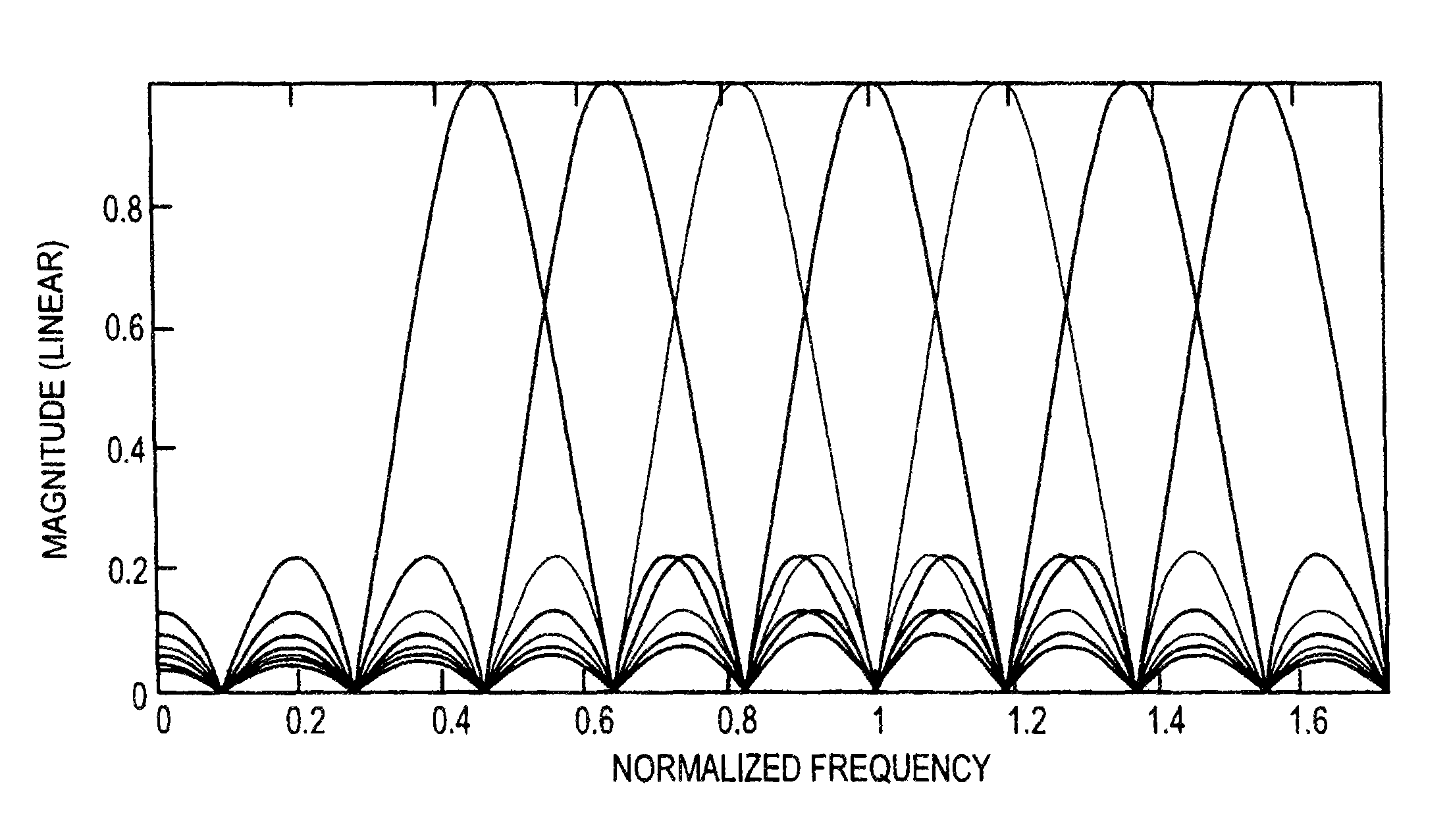
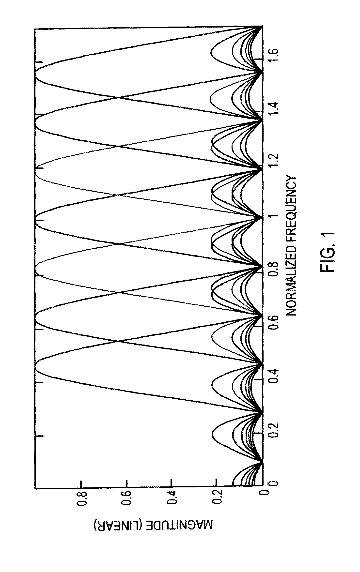
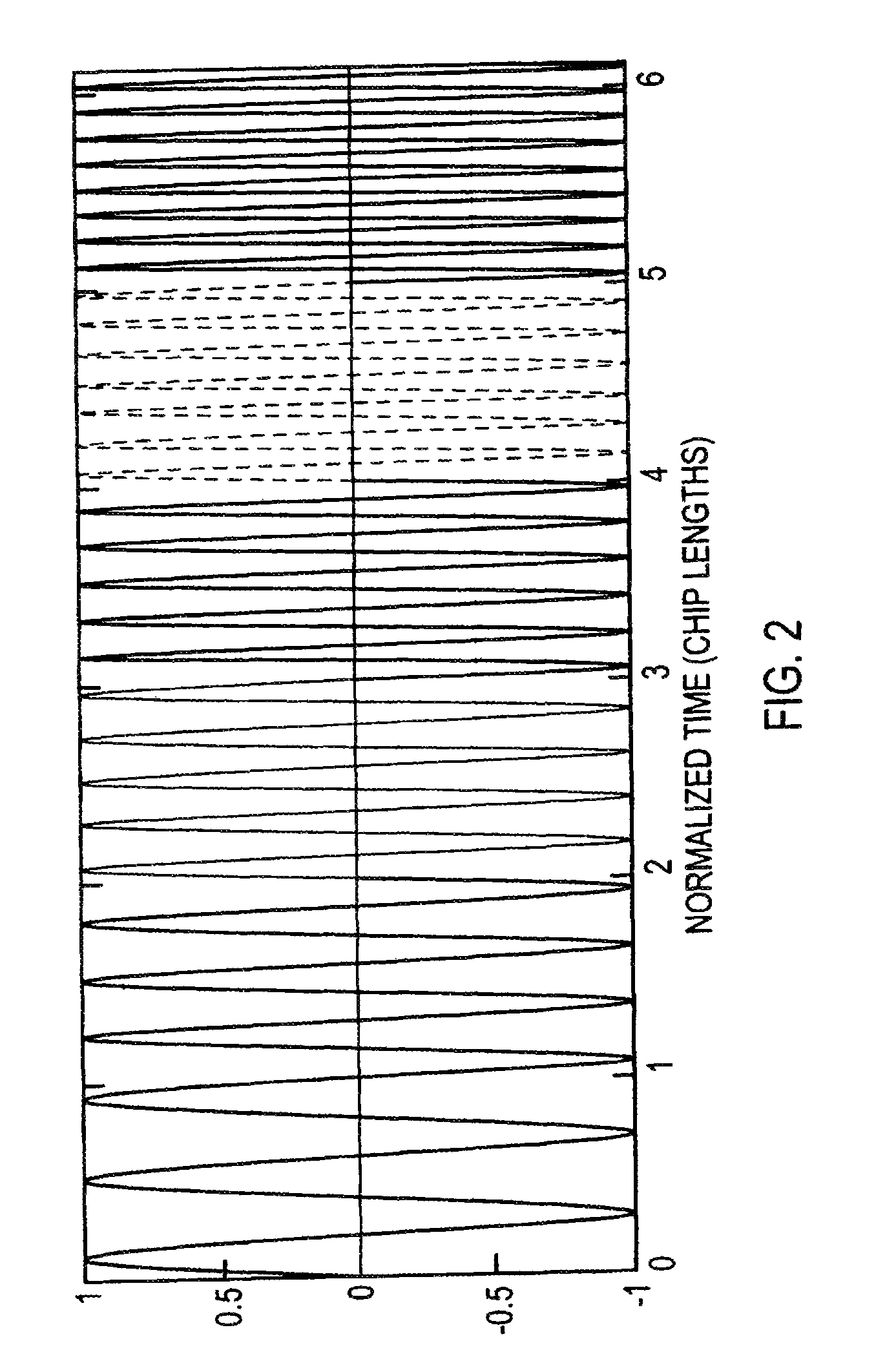
[0055]It would be useful to review orthogonal frequency before discussing the method, system apparatus and device for using orthogonal frequency coding of the present invention. Orthogonal frequencies are used to spread the signal bandwidth. The orthogonality condition describes a relationship between the local chip frequencies and their bandwidths. As an example, consider the stepped linear chirp shown in FIG. 1. Seven coherent carriers are used to generate the signal shown. Each chip contains an integer number of carrier half cycles due to the orthogonality condition. Under these conditions, the resulting waveform is continuous. Th...


PUM


Abstract

Methods and systems for coding SAW OFC devices to mitigate code collisions in a wireless multi-tag system. Each device producing plural stepped frequencies as an OFC signal with a chip offset delay to increase code diversity. A method for assigning a different OCF to each device includes using a matrix based on the number of OFCs needed and the number chips per code, populating each matrix cell with OFC chip, and assigning the codes from the matrix to the devices. The asynchronous passive multi-tag system includes plural surface acoustic wave devices each producing a different OFC signal having the same number of chips and including a chip offset time delay, an algorithm for assigning OFCs to each device, and a transceiver to transmit an interrogation signal and receive OFC signals in response with minimal code collisions during transmission.

Description

[0001]This application is a continuation-in-part of U.S. patent application Ser. No. 11 / 508,674 filed on Aug. 23, 2006, now U.S. Pat. No. 7,623,037 issued on Nov. 24, 2009, which claimed the benefit of priority to U.S. Provisional Patent Application No. 60 / 711,278 filed on Aug. 25, 2005 and U.S. patent application Ser. No. 11 / 521,708 filed on Sep. 15, 2006 which claimed the benefit of priority to U.S. Provisional Patent Application No. 60 / 718,575 filed on Sep. 19, 2005.STATEMENT REGARDING FEDERALLY SPONSORED RESEARCH[0002]The subject invention was made with government support under NASA Grant No. NNK07EA38C. The government has certain rights in this invention.FIELD OF THE INVENTION[0003]This invention relates to orthogonal frequency coding and surface acoustic wave devices and, in particular, to methods and systems for surface acoustic wave coding for orthogonal frequency coded devices to reduce code collisions in a multi-tag system.BACKGROUND AND PRIOR ART[0004]The surface acoustic...

Claims


Application Information

Patent Timeline
Patent Type & Authority Patents(United States)
IPC IPC(8): G08B13/14H10N30/80
CPCG06K19/0675G06K19/0672
Inventor MALOCHA, DONALDKOZLOVSKI, NIKOLAI
Owner UNIV OF CENT FLORIDA RES FOUND INC
Learn More