
Method and apparatus for cooling the underside of kiln cars

a technology for cooling the underside and the underside of the car, which is applied in the direction of furnace cooling, furnace types, furnaces, etc., can solve the problems of not providing a perfect seal, sand barrier actually permeable to gas, and seals are far from per

Inactive Publication Date: 2011-05-31
SOLUTION DYNAMICS
View PDF6 Cites 28 Cited by
  • Summary
  • Abstract
  • Description
  • Claims
  • Application Information

AI Technical Summary

Benefits of technology

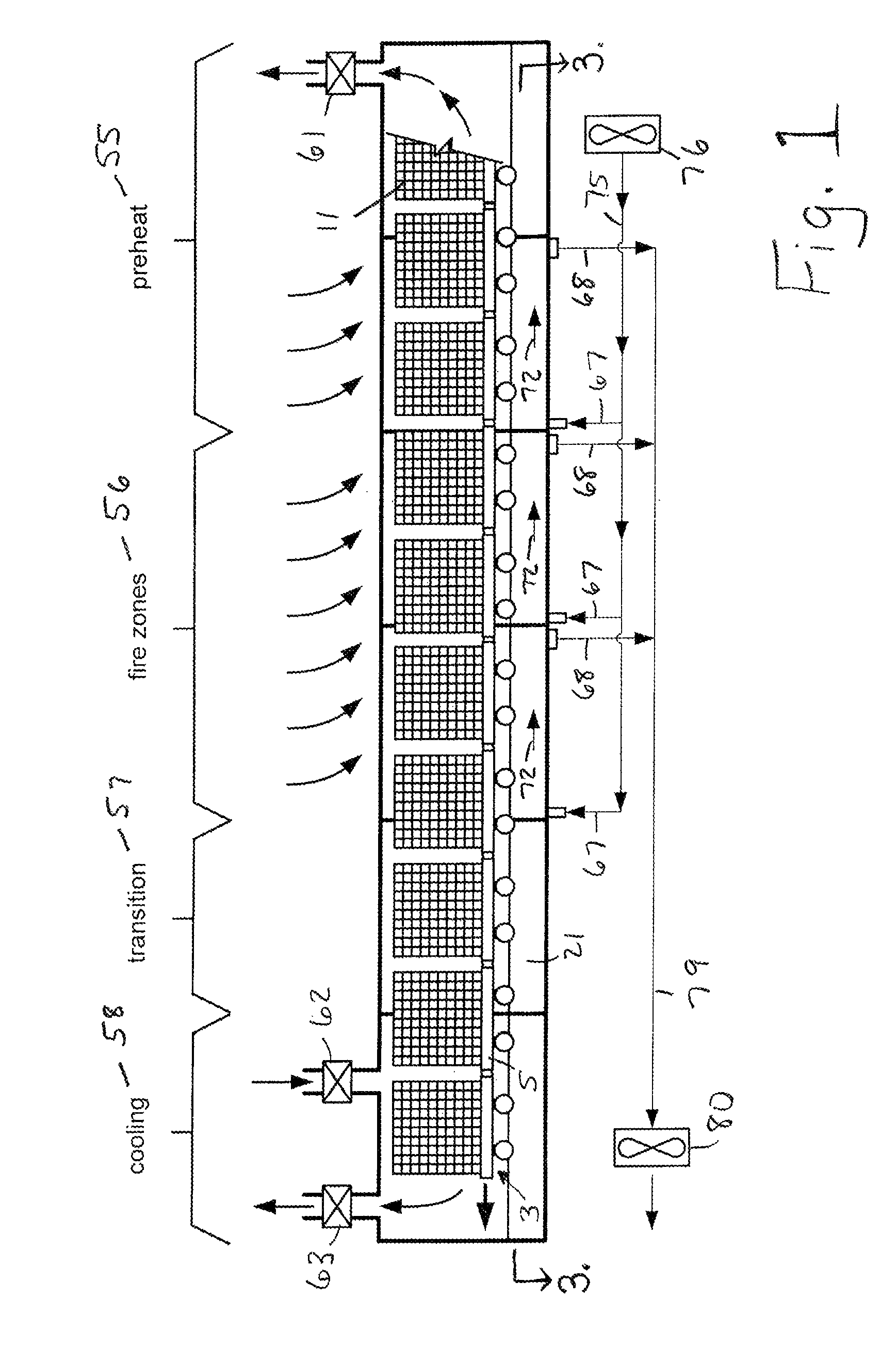
[0011]The improved method and apparatus for cooling the under-car channel of a tunnel kiln while minimizing migration of air between the above-car and under-car channels involves controlling or equalizing the mass flow of cooling air directed through the under-car channel and in particular through individual temperature control zones which match the individual heating zones of the tunnel kiln.
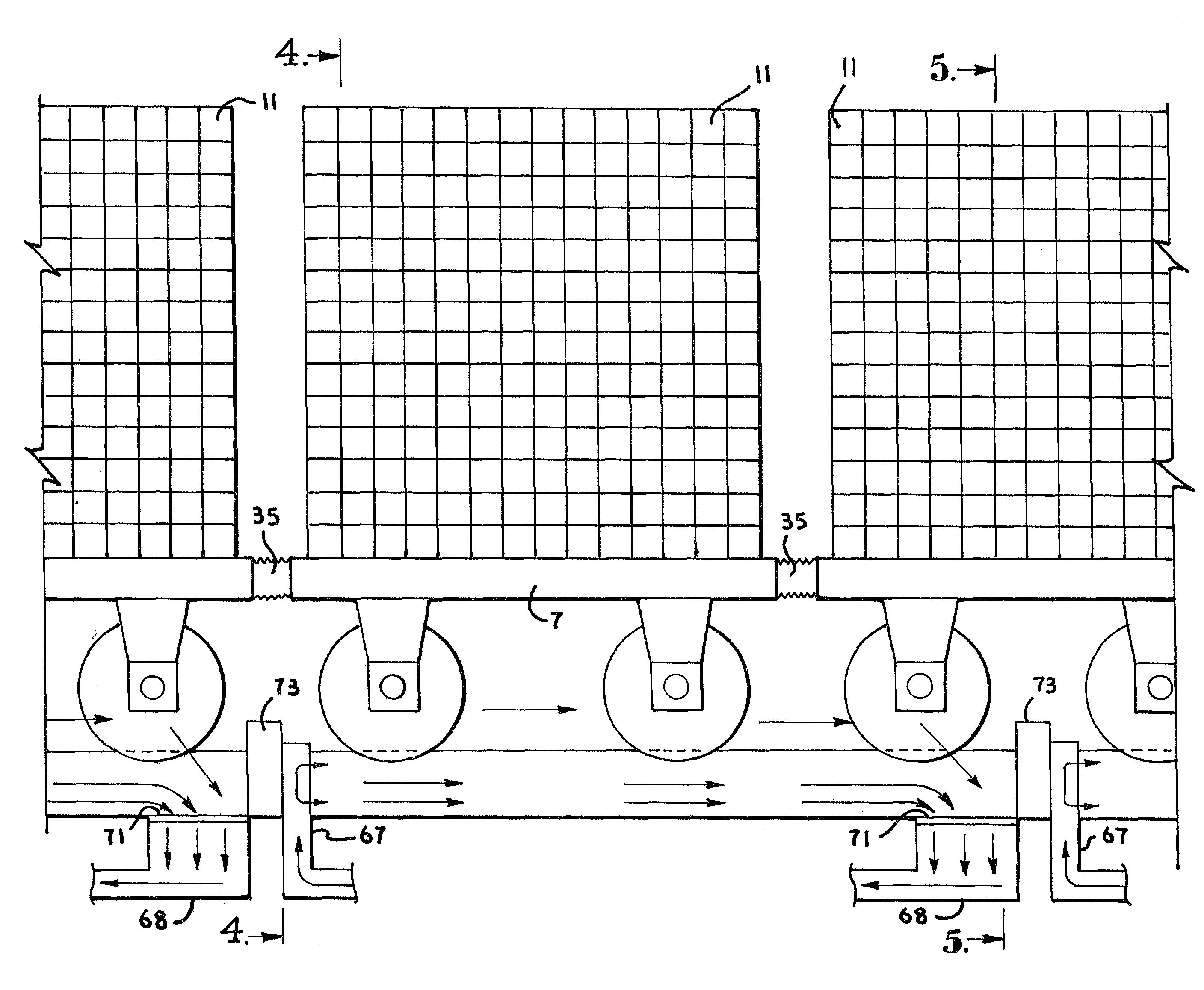
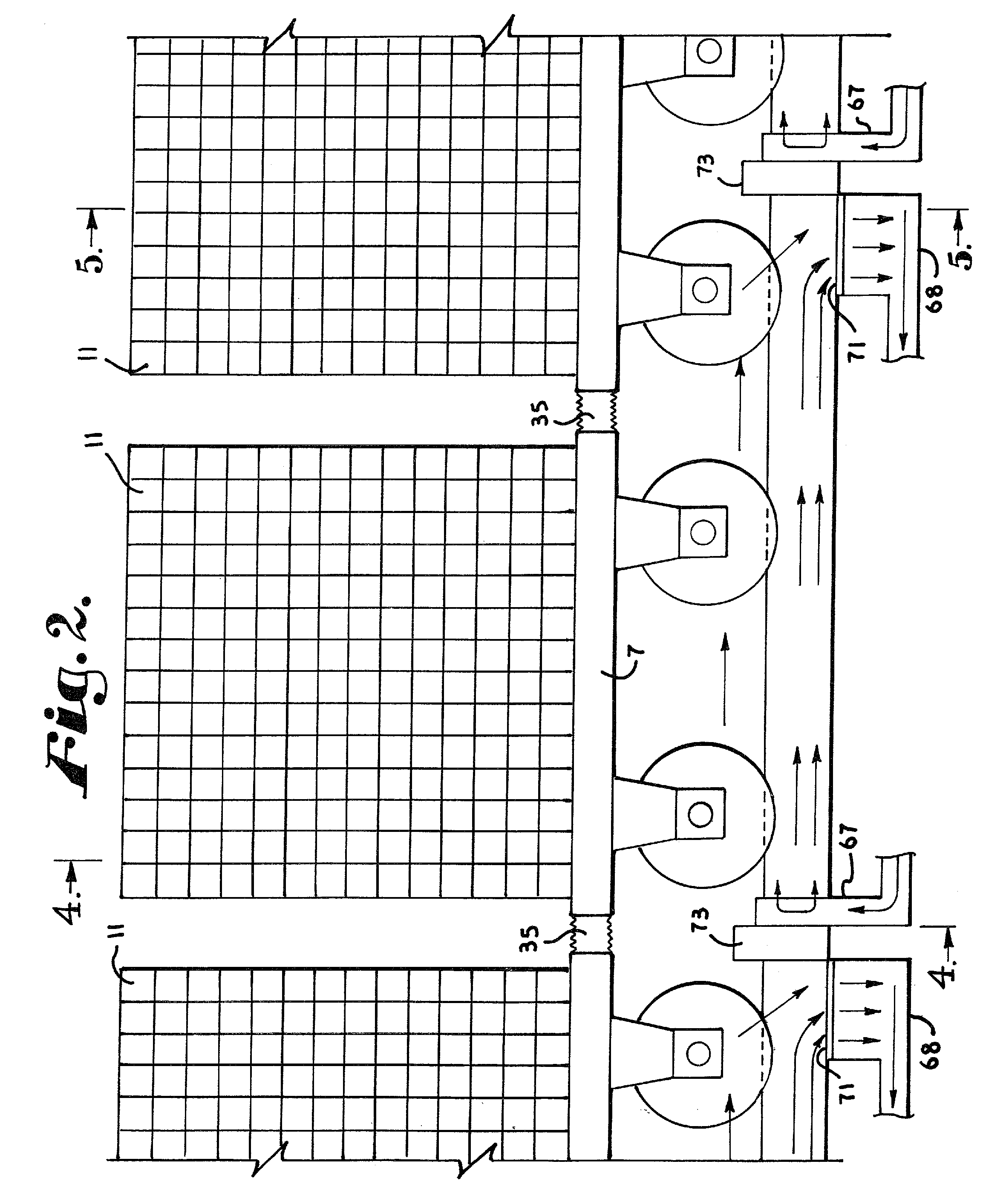
[0014]Individual sub-chambers may be cooled differently as a function of prevailing temperature within that specific sub-chamber. For example, a first firing zone may have a different cooling air mass flow than a second firing zone and the mass flow of the under-car cooling air can be controlled for each specific sub-zone as required by the process parameters required in the respective above-car channels. With the balanced mass flow approach, there is no substantial gas flow into or out of the sub-chamber other than cooling air. Therefore, there is no substantial leakage gas flow between the cooling channel and the firing channel. As a result, the leakage rates of sand filled channels or other types of mechanically attempted “perfect” seals between the above-car firing channel and the under-car cooling channel are much more effective in that the leakage rates are substantially reduced, thereby increasing the net kiln energy efficiency. As an added advantage, the under-car channel individual zones can be cooled at different rates in different sections or sub-chambers as a function of position along the tunnel kiln. Kiln cars can be transported along a rail system in the same plane both inside and outside the tunnel kiln so that lifting or lowering devices are avoided when wet seals are used. This under-car cooling system substantially facilitates movement and circulation for the kiln cars with conventional apparatus and existing facilities which can be retrofitted or converted to practice this present invention.

Problems solved by technology

The purpose of such mechanical seals and sand barriers is to substantially prevent pressure equalization between the under-car channel and the heated above-car channels, the seals are far from perfect.
As a result, the sand barrier actually is permeable to gas and does not provide a perfect seal.
Mechanical and elastic material seals simply wear out and degrade from the excessive kiln temperatures and also do not provide a perfect seal.
A disadvantage of this method is that a portion of the forced air will penetrate the mechanical seals and then the cooling air will have to be heated to very high process temperatures.
This second method also has a disadvantage in that a portion of the forced air will penetrate the mechanical seals and then the cooling air will have to be heated to very high process temperatures.
This third method also has a disadvantage in that a portion of the natural cooling air will penetrate the mechanical seals and then the cooling air will have to be heated to very high process temperatures.
The cooling air penetration in all three cases of the known prior art is partially caused by imperfect and worn mechanical seals, misaligned seals caused by natural degradation of the tunnel kiln structure, and the negative pressure within the above-car channel caused by the kiln exhaust fan, i.e. a pressure imbalance between the under-car channel and above-car channel.
The problems associated with this conventional “sand trough” sealing technique for multi-train kilns are simply an order of magnitude larger than those experienced with a single train kiln.
The long lateral distances and required structure disrupt the gas flow conditions existing in the firing channel.
Also, the increased number of sand-sealed channels in multi-train kilns tunnels increases the infiltration into the above-car channels from the under-car channels, making it more difficult to heat the above-car channel and the material on the car.
For these reasons, multi-train tunnels are not generally constructed for commercial use.

Method used


Image

  • Method and apparatus for cooling the underside of kiln cars
  • Method and apparatus for cooling the underside of kiln cars
  • Method and apparatus for cooling the underside of kiln cars

Examples


Embodiment Construction

[0021]Referring to the drawings in more detail, a schematic view of a tunnel kiln 1 with a kiln car train 3 passing therethrough is shown in FIG. 1. The kiln car train 3 comprises a plurality of kiln cars 5 coupled together in end to end alignment. Referring to FIG. 2, which is an enlarged and fragmentary view of the kiln car train 3 in the tunnel kiln 1. Each of the kiln cars 5 includes a deck 7 supported by an undercarriage 9. Articles to be cured, such as bricks 11, are stacked on and supported by the deck 7 and the undercarriage facilitates passage of the kiln car 5 through the tunnel 1. An undercarriage cooling system 13 is incorporated into the tunnel kiln 1 to cool the undercarriages 9 of the kiln cars 5 as the train 3 passes through the tunnel kiln 1. It is to be understood that the drawings provided, including schematic views, are not drawn to scale and relative proportions have been modified to allow the drawings to fit the space provided. In addition, the relative proport...


PUM


Abstract

An improved method and apparatus for cooling the under-car channel of a tunnel kiln while minimizing migration of air between the above-car and under-car channels involves controlling or equalizing the mass flow of cooling air directed through the under-car channel and in particular through individual undercarriage cooling zones which can match individual heating zones of the tunnel kiln.

Description

CROSS REFERENCE TO RELATED APPLICATIONS[0001]This application claims the benefit of the prior filed, co-pending application Ser. No. 60 / 961,285 filed Jul. 20, 2007.FIELD OF INVENTION[0002]This invention is directed to a method and apparatus for cooling the undersides (under-car channels) of kiln cars carrying a load of material to be heated through a tunnel type kiln. The apparatus and method of the present invention focus on equalizing the mass flow rate of the supply air and exhaust air through the system and in particular through individual temperature control zones which match the individual heating zones of the tunnel kiln.BACKGROUND OF THE INVENTION[0003]Tunnel kilns are elongated kilns through which a train of kiln cars is advanced to heat or fire ceramic materials, such as bricks, supported on the kiln cars. The kiln car train typically travels on rails running through the tunnel. The material to be heated is supported on a flat deck which in turn is supported on an undercar...

Claims


Application Information

Patent Timeline
IPC IPC(8): F27D15/02
CPCF27B9/20F27B9/262F27D9/00F27D3/123F27D2009/0072
Inventor WOOLSEY, RICK L.
Owner SOLUTION DYNAMICS
Learn More