
Adjustable tissue or nerve cuff and method of use

a nerve cuff and adjustable technology, applied in the field of surgical implantable devices and methods, can solve the problems of nerve damage, increased cost, time-consuming process, etc., and achieve the effects of minimizing the migration of the cuff and potential failure, simple manufacturing, and improved results

Inactive Publication Date: 2012-02-14
ANGELTEAR SOLUTIONS
View PDF21 Cites 29 Cited by
  • Summary
  • Abstract
  • Description
  • Claims
  • Application Information

AI Technical Summary

Benefits of technology

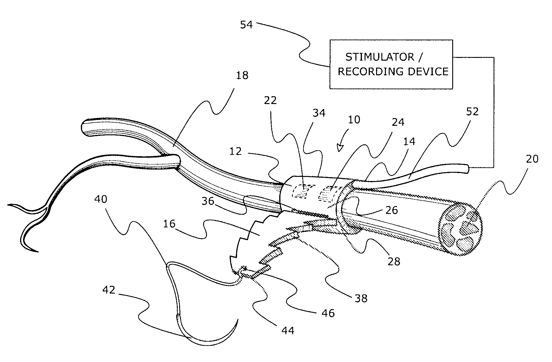
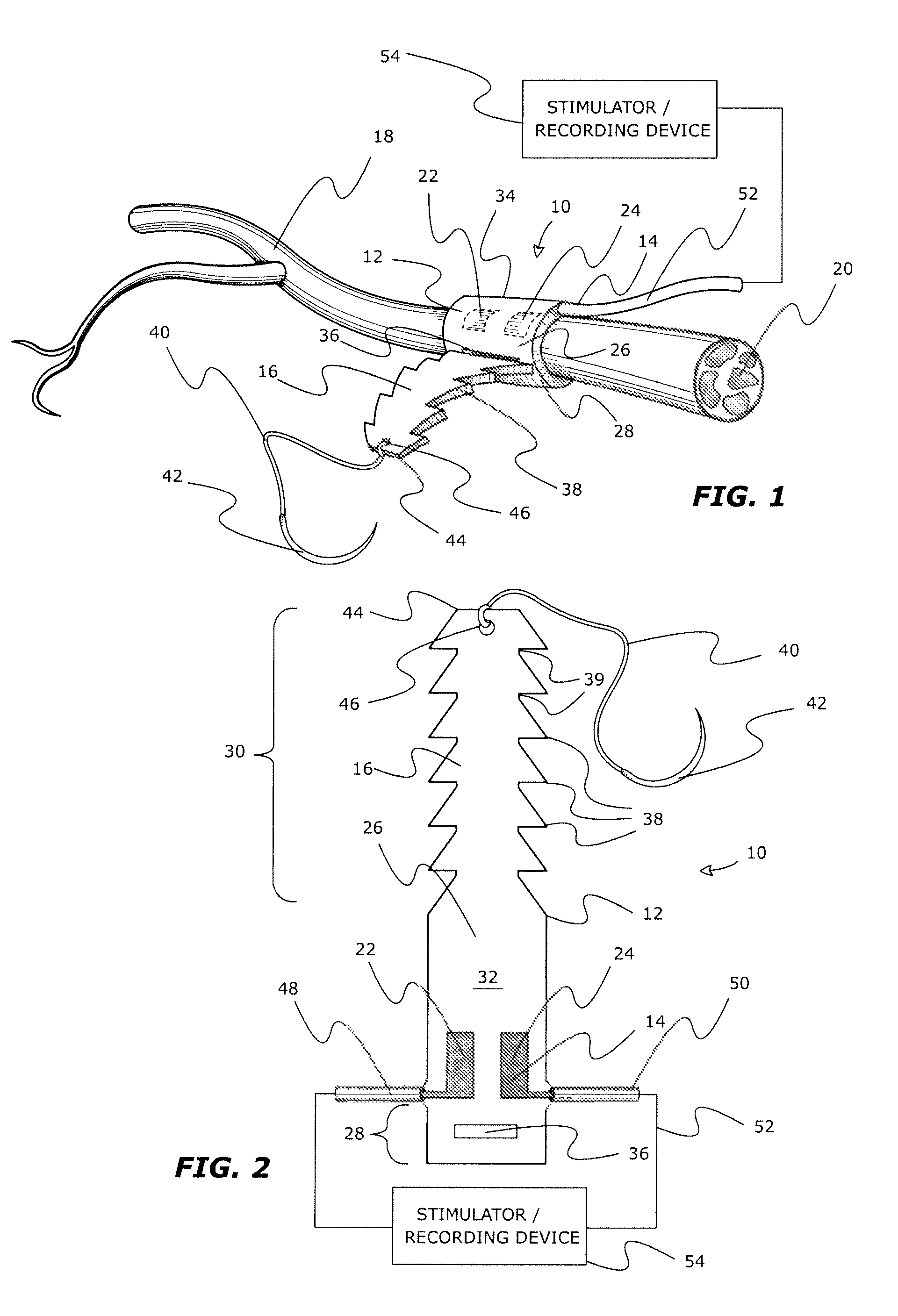
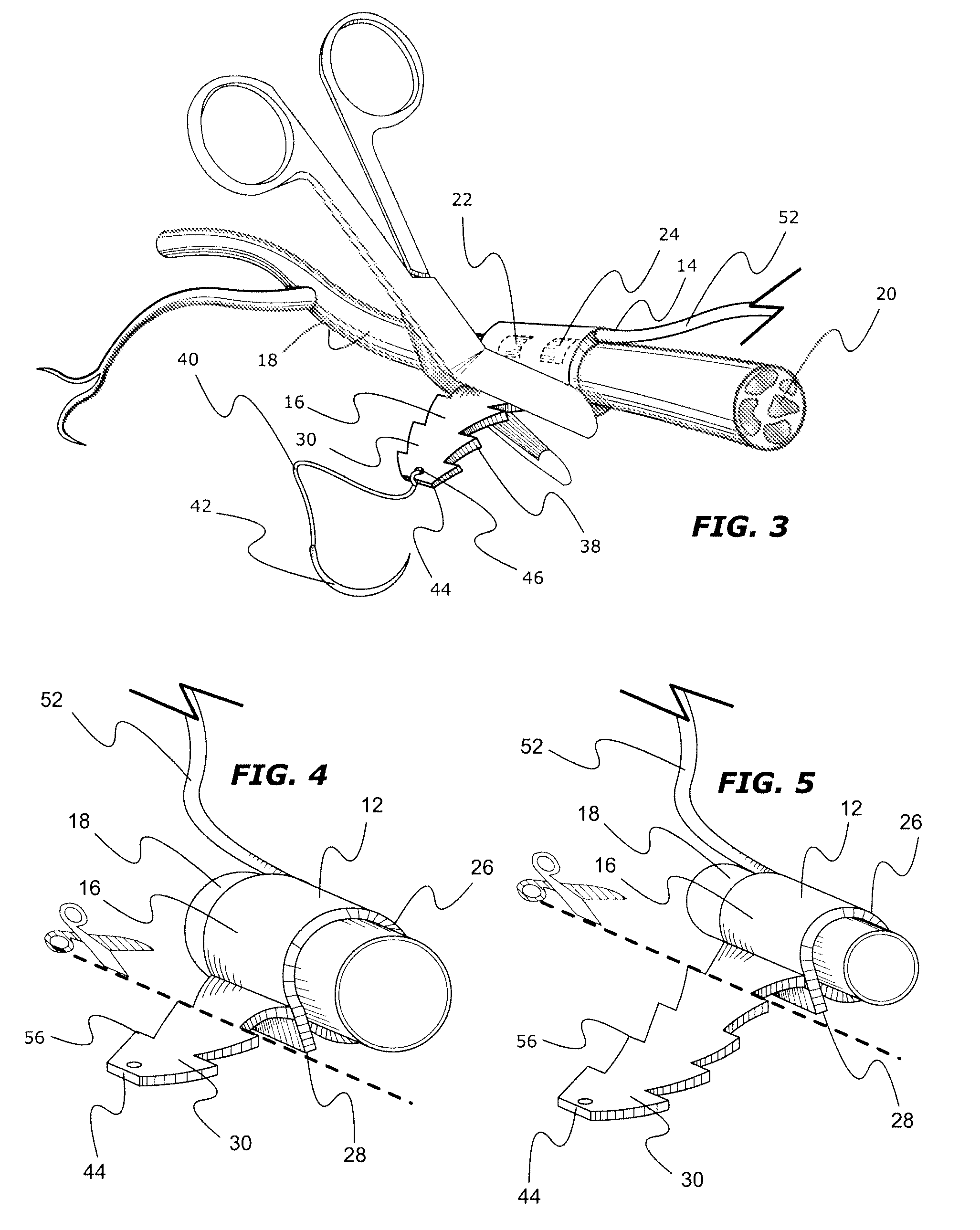
[0017]The method thus provides an intra-operative technique to adjust cuff size around biological tissues, with the option to secure and lock the cuff to a desired size. Multiple sized nerve cuffs are no longer needed since during the implantation the cuff can be tightened or loosened for the best fit. This tissue cuff allows for intra-operative fine tuning. Test stimulations can be carried out and if an inappropriate result is seen the cuff can be moved or readjusted with ease to yield a better result, without tissue damage. Furthermore the cuff can be locked, stitched shut and / or anchored to nearby tissues to minimize migration of the cuff and potential failure.
[0018]Unlike other nerve cuff designs, the cuff of this invention enables simple manufacture with a simple planar 2D process from a flat sheet of substrate material. It can be stamped or laser cut from a flat biocompatible sheet of non-conductive material. The body portion of the cuff may then be attached to conductive elements such as electrode leads. The planar nature of the cuff apparatus also allows for photolithography and electroplating to be used in generating custom conductive elements and electronic circuits onto the body portion of the cuff. The cuff simplicity and size are conducive to endoscopic placement of this invention.

Problems solved by technology

The main draw back to c-shaped nerve cuffs is that the internal diameter of the nerve cuff needs to be estimated prior to the surgery, and hence it can result in loose fitting cuffs if made too large, or too constricting cuffs resulting in nerve damage if made too small.
This can greatly increase costs as multiple sizes need to be made available to the surgeon to minimize problems.
One main draw back is that they need to be wrapped around the nerve, which can be a time consuming process.
This can result in inappropriate contacts being made to the nerve.
Helical cuffs are also susceptible to size constraints.
However, one risk is that damage to the nerve can occur during the installation.
As well, a possible tensile strength decrease can weaken the nerve.
In the case of large rigid structures near the nerve there is a further risk for increasing the incidence of inflammation in response to the mechanical aggravation of the tissues.
The rigidity needed to shape the nerve in a corrugated nerve cuff such as in U.S. Pat. No. 5,634,462 also limits the ability of the cuff to accommodate different nerve sizes, so as above, different size cuffs must be provided for different nerve sizes.
Finally, the corrugations of this type of device are designed to minimize contact points with the nerve, which for some applications limits the nerve surface which can be directly contacted with electrical contacts of nerve interacting devices.

Method used


Image

  • Adjustable tissue or nerve cuff and method of use
  • Adjustable tissue or nerve cuff and method of use
  • Adjustable tissue or nerve cuff and method of use

Examples


example

[0065]The nerve cuff apparatus of this invention in multiple of the preferred embodiments has been tested in numerous animal trials where the application was an electrical nerve cuff. Following successful animal implanting, a plurality of nerve cuff apparatus 180 having the configuration and dimensions shown in FIG. 19 (not drawn to scale) were implanted in a 51 year old spinal cord injured man. The implantation was directed to restore upper extremity hand function in conjunction with a nerve stimulator device as described in U.S. Patent Application No. 2006 / 0184211 A, published Aug. 17, 2006, to Gaunt et al. The nerve cuff straps 182 were each laser cut out of a biocompatible silicone rubber sheet 0.254 mm thick. The implanted nerve cuff apparatus 180 included a monopolar conductor 184 attached to the body portion 186 of the nerve cuff strap 182 with a silicone rubber adhesive 188, cured prior to sterilization and implantation. The tail end portion 190 was formed with tear drop sha...


PUM


Abstract

An implantable adjustable body tissue cuff, apparatus and method. The cuff is an elastomeric strap of biocompatible non-conductive material. The strap's tail and head provide adjustable length fastening by a) the tail being formed with longitudinally spaced, laterally paired locking projections and the head being formed with one or more locking apertures; or b) the tail being formed with longitudinally spaced locking apertures and the head being formed with one or more laterally paired locking projections. The locking projection shape allows for passage through the locking aperture, while restricting movement in a reverse direction. The cuff accommodates devices such as tissue stimulators or recorders, with conductive elements attached, imbedded, or printed on the strap body. The cuff is intra-operatively adjusted to optimize placement and contact between conductive elements and body tissue, without tissue damage. This cuff accommodates varying tissue diameters and simplifies manufacture and surgical placement.

Description

CROSS-REFERENCE TO RELATED APPLICATION[0001]This application claims priority from U.S. Provisional Patent Application No. 61 / 029,269 filed Feb. 15, 2008, which is incorporated by reference herein in its entirety to the extent that there is no inconsistency with the present disclosure.BACKGROUND OF THE INVENTION[0002]The invention relates to the field of surgically implantable devices and methods in the biomedical field. Implantable cuffs have been used for the stimulation and recording of biological tissues, particularly nerves. Stimulation of the nervous system with nerve cuffs can result in recovery of lost sensory or motor function in individuals with neurological deficits. An example of such an application is the Freehand™stimulator (Neurocontrol Corporation, Ohio, USA) that can restore a degree of hand function in an individual with a spinal cord injury. Recording has also been performed with implantable cuffs. Recording nerve function can relay vital information back to a proc...

Claims


Application Information

Patent Timeline
Patent Type & Authority Patents(United States)
IPC IPC(8): A61N1/00
CPCA61B5/04001A61B5/4818A61N1/0551A61B5/0031A61N1/05A61N1/0556A61N1/0558A61B5/4041A61B5/24
Inventor KOWALCZEWSKI, JAN
Owner ANGELTEAR SOLUTIONS
Learn More