
X-ray fluorescence spectrometer

a fluorescence spectrometer and x-ray technology, applied in the field of x-ray fluorescence spectrometers, can solve the problems of inability to achieve a sufficiently high precision, and the precision of analysis for a very small amount of sulfur is insufficient to accommodate the recent standard value, so as to achieve the effect of improving the lower limit of detection

Inactive Publication Date: 2011-05-24
RIGAKU CORP
View PDF9 Cites 4 Cited by
  • Summary
  • Abstract
  • Description
  • Claims
  • Application Information

AI Technical Summary

Benefits of technology

The present invention provides an X-ray fluorescence spectrometer for measuring the concentration of sulfur in a sample. The spectrometer includes an X-ray tube, a spectroscopic device, and a detector. The X-ray tube generates primary X-rays that are directed towards the sample and a portion of the X-rays is monochromated by the spectroscopic device. The monochromated X-rays are then detected by the detector. The spectrometer is designed to reduce the influence of scattered X-rays and the detector gas used contains either neon or helium to minimize background intensity. The use of a target with an element including chromium or titanium in the X-ray tube and a corresponding X-ray filter with a predetermined transmittance for the element results in improved detection of very small amounts of sulfur and improved precision in the analysis of the concentration of sulfur.

Problems solved by technology

The X-ray fluorescence analysis has hitherto been employed to analyze the sulfur concentration in the fuel oil such as, for example, gasoline, diesel oil or kerosene, but is incapable of providing a sufficient precision of analysis and the lower limit of detection at a concentration lower than the uppermost limit determined by the current standards.
For this reason, the background, when converted into the concentration of sulfur, is as large as 100 ppm and the precision of analysis for a very small amount of sulfur is in no way sufficient to accommodate the recent standard value.
Even the X-ray fluorescent spectrometer including the X-ray tube having the scandium target and the scandium foil filter, and the X-ray fluorescent spectrometer including the X-ray tube having the scandium target and the titanium foil filter, which are the X-ray fluorescent spectrometers disclosed in the Patent Document 1 below, have problems similar to that discussed above and accordingly the energy dispersive X-ray fluorescent spectrometer is incapable of achieving the lower limit of detection and a sufficiently precision even though it makes use of an X-ray tube, having a target suitable to analysis of sulfur, and a primary beam filter.
However, it has not yet been understood that the higher order lines such as the second order line of the continuous X-rays diffracted by the spectroscopic device result in an escape peak and this forms a background, resulting in error in analysis and deterioration in analytical precision, and this phenomenon has now been discovered.
As discussed above, with the conventional wavelength dispersive X-ray fluorescent spectrometer, sulfur cannot be sufficiently excited if the primary beam filter such as, for example, an aluminum foil is used, and a quantitative analysis of a very small amount of sulfur contained in the fuel oil has been considered difficult to achieve.
Also, the second order line of the scattered X-ray of the continuous X-rays from the X-ray tube causes an escape peak attributable to the argon gas in the proportional counter, which in turn interfere the S—Kα line, which is analytical line of sulfur, to thereby form a large background, making it difficult to analyze a very small amount of sulfur with high precision.
Also, since the background is high, variation of the background among samples adversely affects the analytical values, resulting in an analytical errors.[Patent Document 1] JP Laid-open Patent Publication No.

Method used


Image

  • X-ray fluorescence spectrometer
  • X-ray fluorescence spectrometer
  • X-ray fluorescence spectrometer

Examples


Embodiment Construction

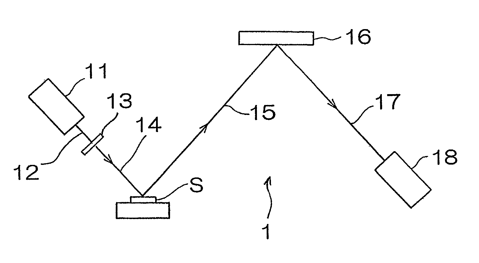
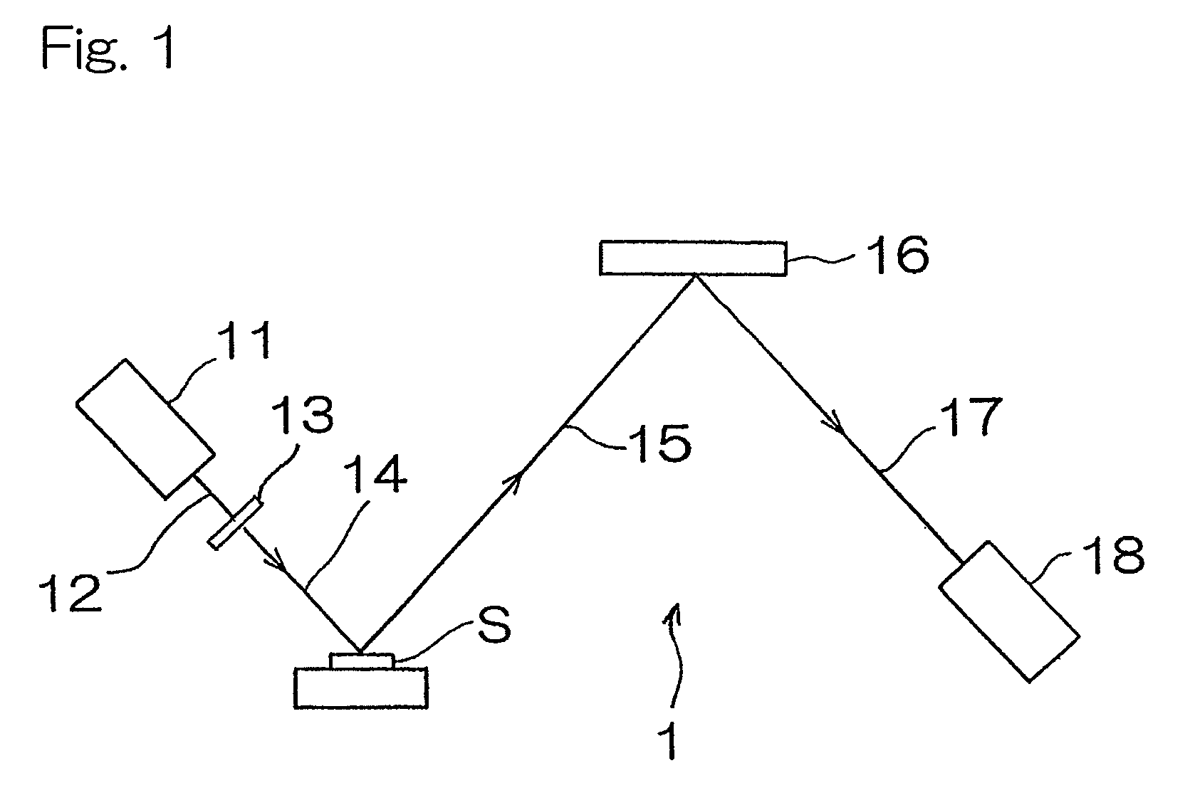
[0041]Hereinafter, an X-ray florescence spectrometer according to a first preferred embodiment of the present invention will be described. As shown in FIG. 1, the X-ray fluorescence spectrometer for measuring the concentration of sulfur contained in a diesel oil, which is a kind of fuel oil, includes a chromium X-ray tube 11 having a target of chromium metal, an X-ray filter 13 for transmitting 60% or more of Cr—Kα line of primary X-rays 12 emitted from the chromium X-ray tube and comprised of, for example, an aluminum foil of 12 μm in thickness, a spectroscopic device 16 for monochromating fluorescent X-rays 15 emitted from a sample S, and comprised of, for example, graphite, and a sealed proportional counter 18 filled with a detector gas of, for example, neon gas and operable to detect fluorescent X-rays 17 which have been monochromated.

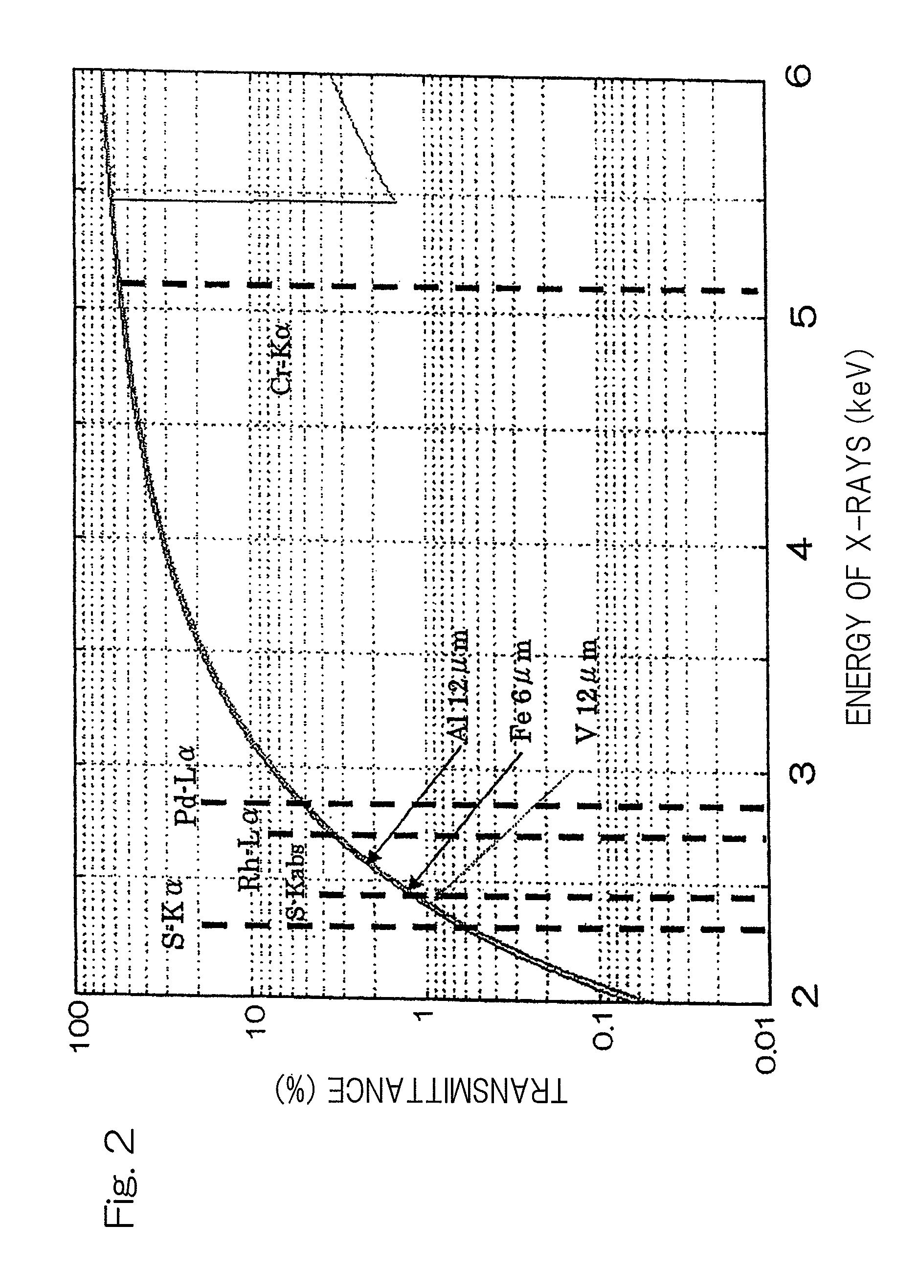
[0042]FIG. 2 illustrates respective X-ray transmittances of energies when an filter having aluminum of 12 μm in thickness, a filter having iron of...


PUM

PropertyMeasurementUnit
transmittanceaaaaaaaaaa
thicknessaaaaaaaaaa

Abstract

An X-ray fluorescence spectrometer for measuring the concentration of sulfur contained in a sample (S), by irradiating the sample (S) with primary X-rays from an X-ray tube (11), monochromating fluorescent X-rays emitted from the sample (S) with a spectroscopic device, and detecting monochromated fluorescent X-rays with an X-ray detector. The spectrometer includes the X-ray tube (11) having a target with an element including chromium, an X-ray filter (13) disposed on a path of travel of X-rays between the X-ray tube (11) and the sample (S) and having a predetermined transmittance for Cr—Kα line from the X-ray tube (11) and made of a material which is an element of which absorption edges do not exist between energies of S—Kα line and Cr—Kα line, and a proportional counter (18) having a detector gas containing a neon gas or a helium gas.

Description

BACKGROUND OF THE INVENTION[0001]The present invention relates to an X-ray fluorescence spectrometer for analyzing sulfur contained in a sample.[0002]The concentration of sulfur contained in fuel oil such as, for example, gasoline, diesel oil or kerosene has its uppermost limit determined by the standards and is, accordingly, measured during or after refinement of the crude oil for administrative or control purpose. In recent years, regulations have become tighter not only in Japan, but also in the United States and European countries and the uppermost limit in the relevant standards has come to be lowered, accompanied by the requirement to analyze even a very small quantity, say, 5 ppm or smaller, of sulfur.[0003]The X-ray fluorescence analysis has hitherto been employed to analyze the sulfur concentration in the fuel oil such as, for example, gasoline, diesel oil or kerosene, but is incapable of providing a sufficient precision of analysis and the lower limit of detection at a con...

Claims


Application Information

Patent Timeline
Patent Type & Authority Patents(United States)
IPC IPC(8): G01N23/223
CPCG01N23/223G01N2223/076
Inventor KATAOKA, YOSHIYUKIKOHNO, HISAYUKIYAMASHITA, NOBORUDOI, MAKOTO
Owner RIGAKU CORP
Learn More