Lubrication system for a multi-spindle automatic screw machine

a multi-spindle screw and lubrication system technology, applied in the direction of turning machine accessories, mechanical equipment, manufacturing tools, etc., can solve the problems of '376 patent with a large path of potential lubricant leakage, etc., to facilitate lubricant flow, reduce the effect of effective area reduction, and reduce the potential leakage path of lubricant passing

Active Publication Date: 2011-05-24
BRINKMAN PROD INC
View PDF18 Cites 2 Cited by
  • Summary
  • Abstract
  • Description
  • Claims
  • Application Information

AI Technical Summary

Benefits of technology

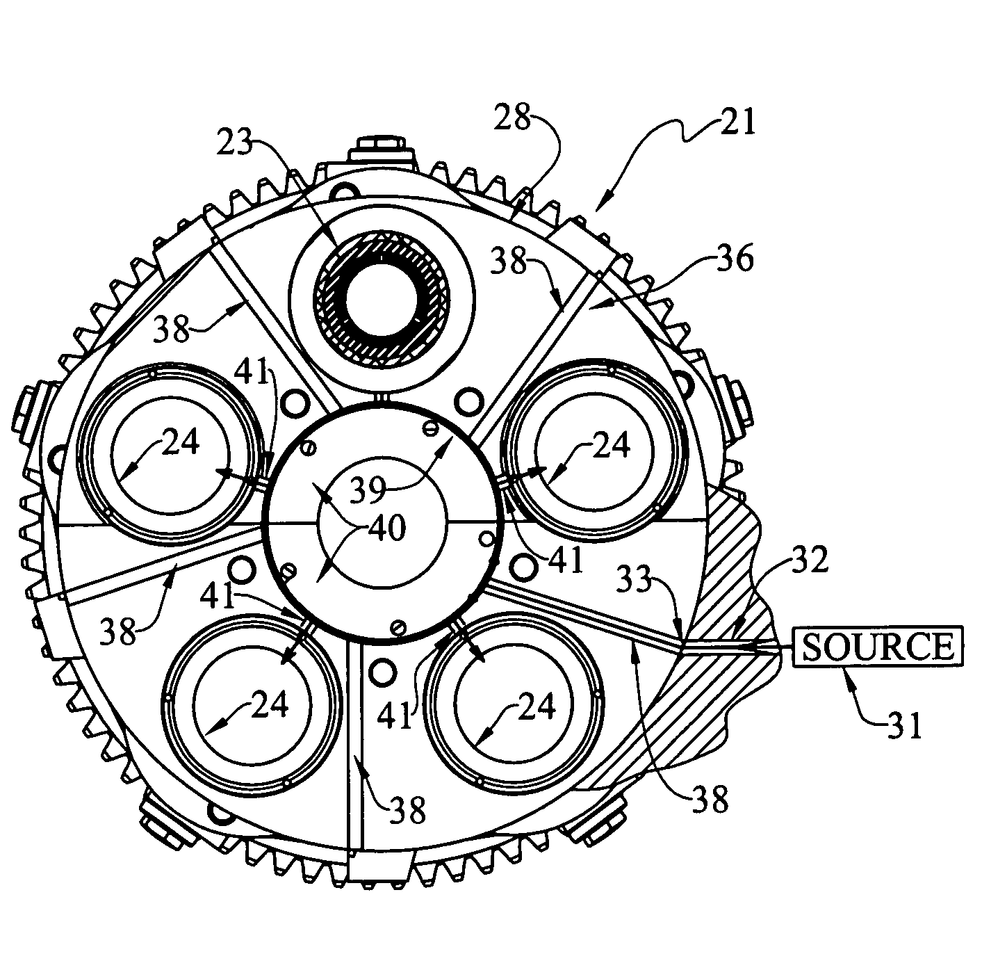
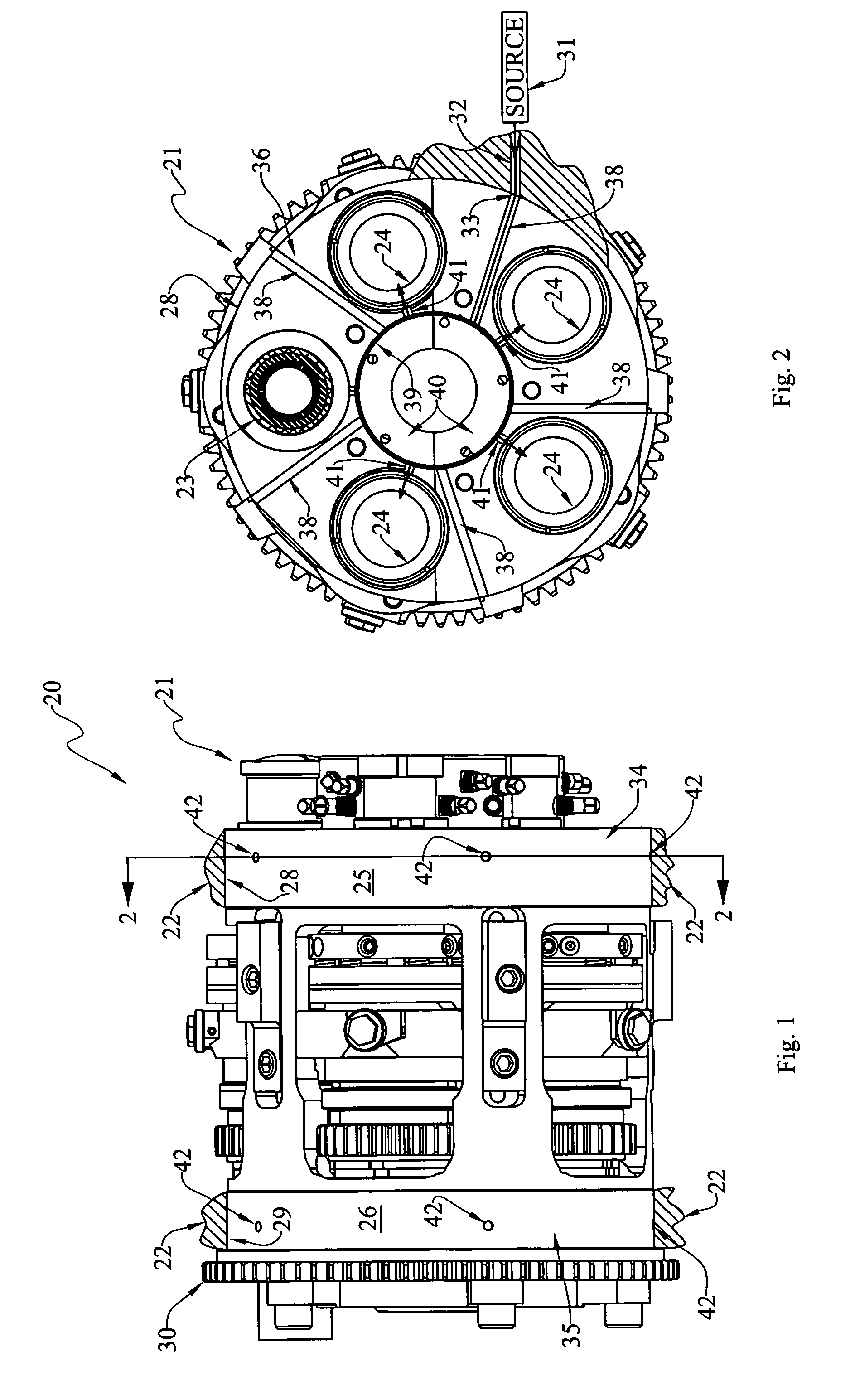
[0023]Another object is to provide a simplified lubrication system that minimizes the reduction of effective area between facing bearing surfaces of a head and body.
[0024]Another object is to provide a simplified lubrication system that greatly reduces the potential leakage path for lubricant passing between the body and head.
[0025]Another object is to provide a simplified lubrication system that facilitates lubricant flow to the spindles in the lowermost index positions, where most heavy machining and stock removal occurs.

Problems solved by technology

While the '376 patent does disclose an operable and functional lubrication system, it also has its problems.
Second, the annular groove provides a long path for potential lubricant leakage.
Thus, the '376 patent has a large path of potential lubricant leakage.

Method used


Image

  • Lubrication system for a multi-spindle automatic screw machine
  • Lubrication system for a multi-spindle automatic screw machine
  • Lubrication system for a multi-spindle automatic screw machine

Examples


Embodiment Construction

[0032]At the outset, it should be clearly understood that like reference numerals are intended to identify the same structural elements, portions or surfaces consistently throughout the several drawing figures, as such elements, portions or surfaces may be further described or explained by the entire written specification, of which this detailed description is an integral part. Unless otherwise indicated, the drawings are intended to be read (e.g., cross-hatching, arrangement of parts, proportion, degree, etc.) together with the specification, and are to be considered a portion of the entire written description of this invention. As used in the following description, the terms “horizontal”, “vertical”, “left”, “right”, “up” and “down”, as well as adjectival and adverbial derivatives thereof (e.g., “horizontally”, “rightwardly”, “upwardly”, etc.), simply refer to the orientation of the illustrated structure as the particular drawing figure faces the reader. Similarly, the terms “inwa...


PUM

PropertyMeasurementUnit
diameteraaaaaaaaaa
total lengthaaaaaaaaaa
diametersaaaaaaaaaa

Abstract

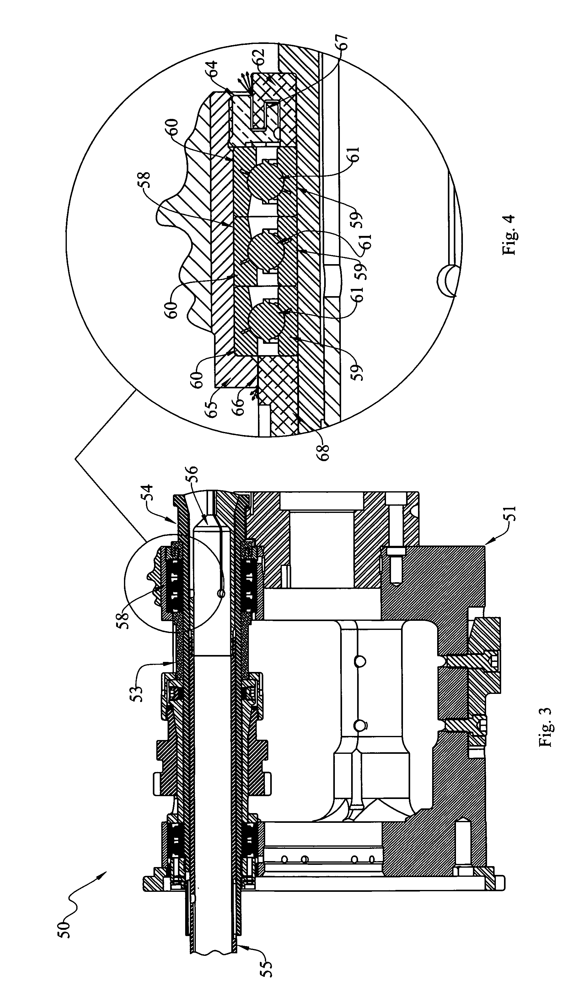
An automatic screw machine (20) has a body (22), and a head (21) that is rotatably mounted on the body and that is adapted to be selectively rotated relative to the body between any of a plurality of index positions. The body and head have closely-spaced and facing bearing surfaces (25, 28 and 26, 29), have spindles (23) journalled on the head for rotation relative thereto, and have a source of pressurized lubricant. The improvement broadly includes: at least one body passageway (32) communicating the source with the body bearing surface, the intersection of each body passageway with the body bearing surface defining a body port (33); a head passageway (36) communicating the head bearing surface with the spindle, the intersection of said head passageway with said head bearing surface defining at least one head port (42); and the body and head passageways being so configured and arranged such that lubricant may flow from the source to the spindle only when the head is in the vicinity of the index position such that the body and head ports overlap one another.

Description

TECHNICAL FIELD[0001]The present invention relates generally to lubrication systems for multi-spindle screw machines, and, more particularly, to an improved lubrication system that is particularly adapted for use with a Model B Davenport® five-spindle automatic screw machine.BACKGROUND ART[0002]The terms “machine tool” and “screw machine” are used to describe two different items of machinery. These two types are similar in that they are used to effect a machining operation on a workpiece. They differ in that, in the machine tool, the tool is rotated relative to a stationary workpiece; whereas, in a screw machine, the workpiece is held in a rotatable spindle.[0003]Some automatic screw machines have a plurality of workpiece-holding spindles journalled at circularly-spaced locations on a head, which is itself, in turn, rotatably mounted on a stationary body. In some of these machines, five such spindles are journalled on the head. Thus, the head may be rotatably indexed relative to the...

Claims


Application Information

Patent Timeline
Patent Type & Authority Patents(United States)
IPC IPC(8): B23B19/02B23B13/04F16N7/36F16N7/00
CPCB23Q11/123B23Q39/042Y10T82/2524Y10T82/20Y10T82/2562B23Q2220/002
Inventor BELPANNO, SANDRO G.HUGICK, JAMES
Owner BRINKMAN PROD INC
Why Eureka
Try Eureka