Drive circuit
a high-frequency agitation and circuit technology, applied in the direction of generator/motor, mechanical vibration separation, spraying apparatus, etc., can solve the problems of unsuitable lc circuit for driving a piezoelectric crystal, unsuitable lc circuit, and unsatisfactory high-voltage square wave signal harmonic content, etc., to achieve simple and cost-effective
- Summary
- Abstract
- Description
- Claims
- Application Information
AI Technical Summary
Benefits of technology
Problems solved by technology
Method used
Image
Examples
Embodiment Construction
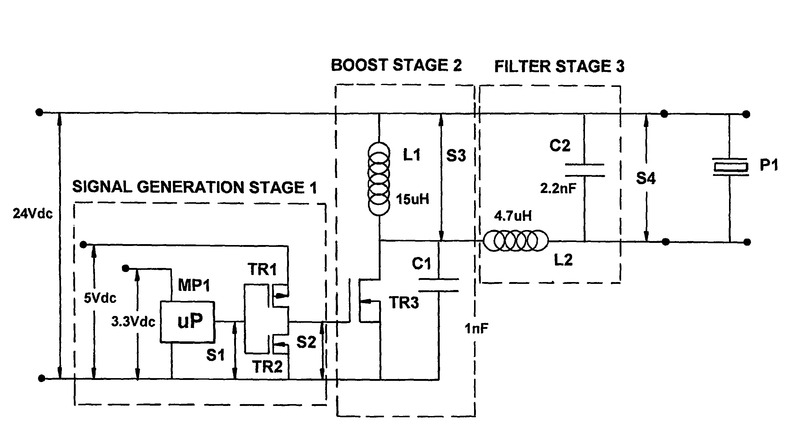
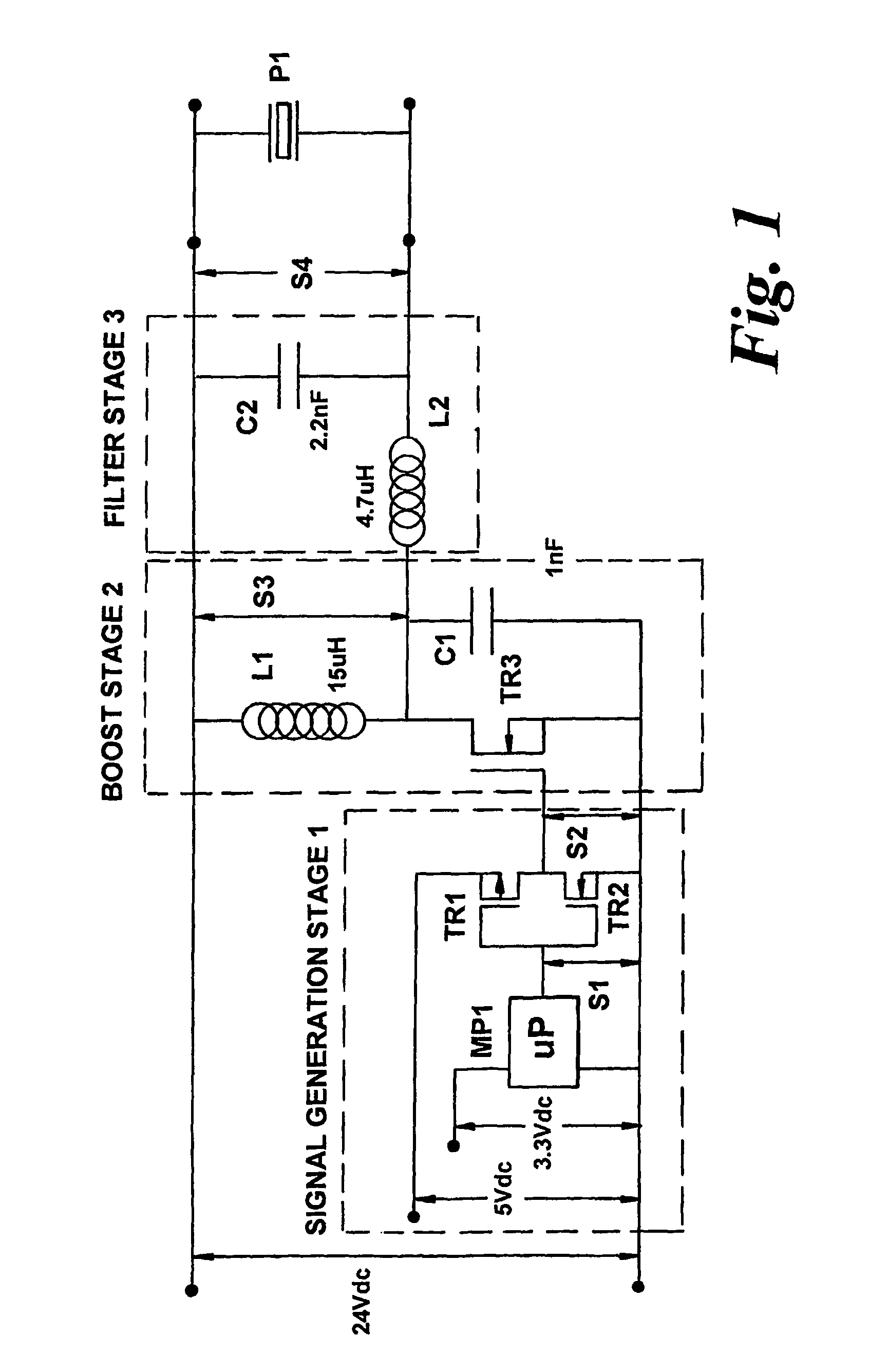
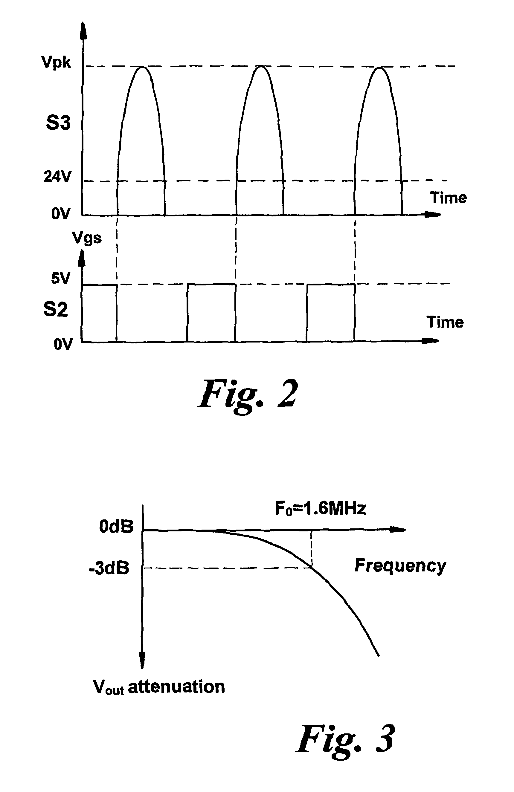
[0018]FIG. 1 shows a drive circuit according to the invention. The drive circuit is powered by a DC power source (not shown). The DC power source originates from an AC / DC converter powered by a mains electricity supply. The drive circuit comprises three stages: a signal generation stage 1, a boost stage 2 and a filter stage 3. The first stage is the signal generation stage 1. The signal generation stage 1 comprises a microprocessor unit MP1 for generating a synchronisation signal at, say, 1660 KHz. The microprocessor unit MP1 is supplied at low voltage, for example 3.3 V. This microprocessor unit MP1 includes a phase-locked loop for multiplying the synchronisation signal to the required drive frequency. The output from the microprocessor unit MP1 is connected to a pair of complementary push-pull Metal Oxide Semiconductor Field Effect Transistors (MOSFETs) TR1, TR2. MOSFET TR1 is a low power p-channel MOSFET, and MOSFET TR2 is a low power n-channel MOSFET. The pair of MOSFETs TR1, TR...
PUM
 Abstract
Description
Claims
Application Information
 - R&D
- Intellectual Property
- Life Sciences
- Materials
- Tech Scout
- Unparalleled Data Quality
- Higher Quality Content
- 60% Fewer Hallucinations
Browse by: Latest US Patents, China's latest patents, Technical Efficacy Thesaurus, Application Domain, Technology Topic, Popular Technical Reports.
© 2025 PatSnap. All rights reserved.Legal|Privacy policy|Modern Slavery Act Transparency Statement|Sitemap|About US| Contact US: help@patsnap.com


