
Adjustable railing post bracket

a railing post and adjustable technology, applied in the direction of bracing pipes, basic electric elements, fastening means, etc., can solve the problems of preventing subsequent adjustment and the limitation of leveling of railing posts in these brackets, and achieve the effect of convenient mounting

Inactive Publication Date: 2011-05-17
ALUSPEK PRODS
View PDF8 Cites 6 Cited by
  • Summary
  • Abstract
  • Description
  • Claims
  • Application Information

AI Technical Summary

Benefits of technology

Enables full leveling and re-leveling of the rail post on any surface, including those that settle, without the need for cement, ensuring the rail remains stable and secure over time.

Problems solved by technology

However, these methods prevent adjustment of the rail post bracket after the concrete cures and requires the rail to be level before it is fixed into position, thereby preventing subsequent adjustment.
However, the adjustment of the rail post in these brackets still limits leveling because it can only be adjusted laterally.
However, these brackets are not adjustable and therefore if the surface they are mounted to is not level the rail railing will not be level.

Method used


Image

  • Adjustable railing post bracket
  • Adjustable railing post bracket
  • Adjustable railing post bracket

Examples


Embodiment Construction

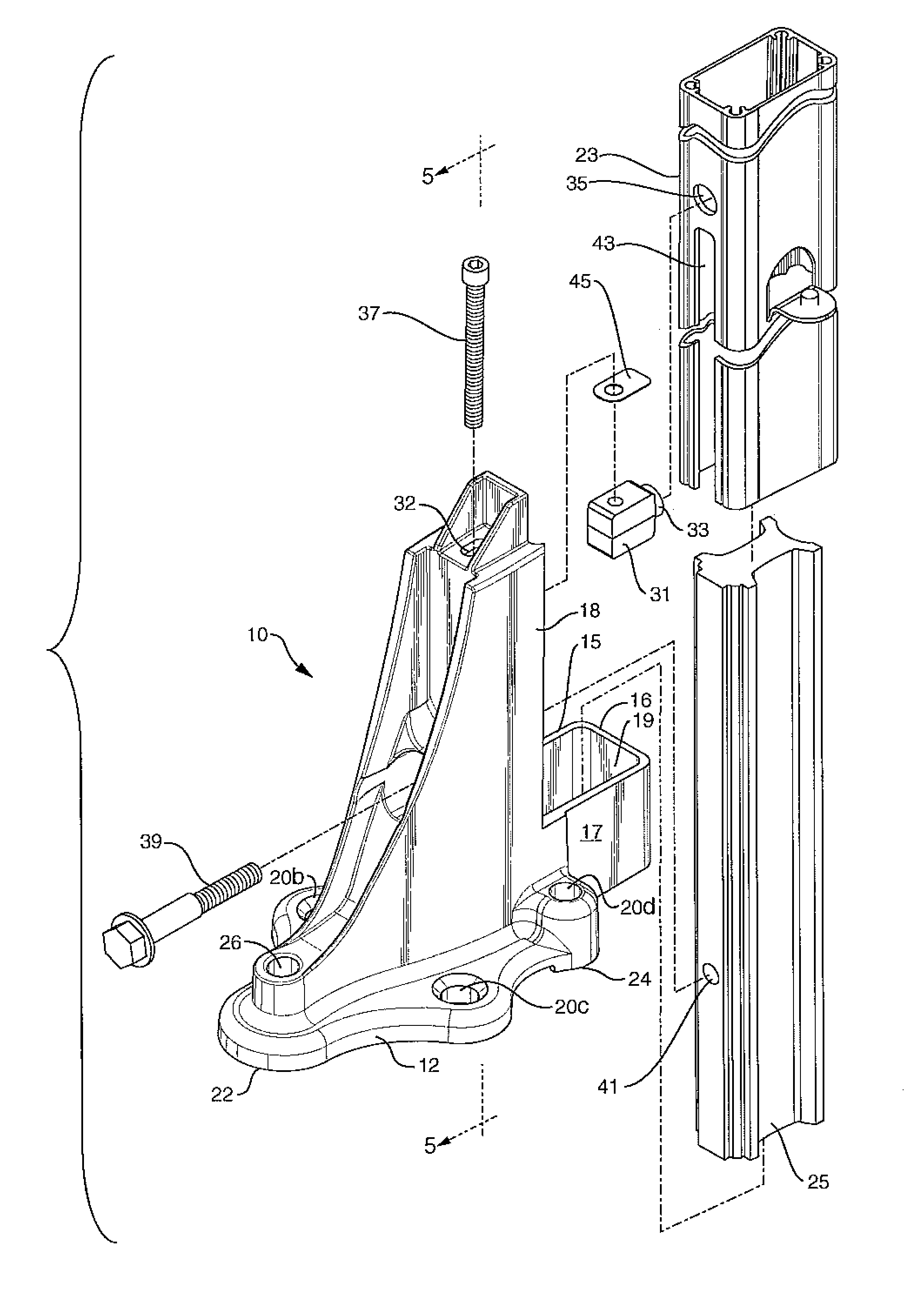
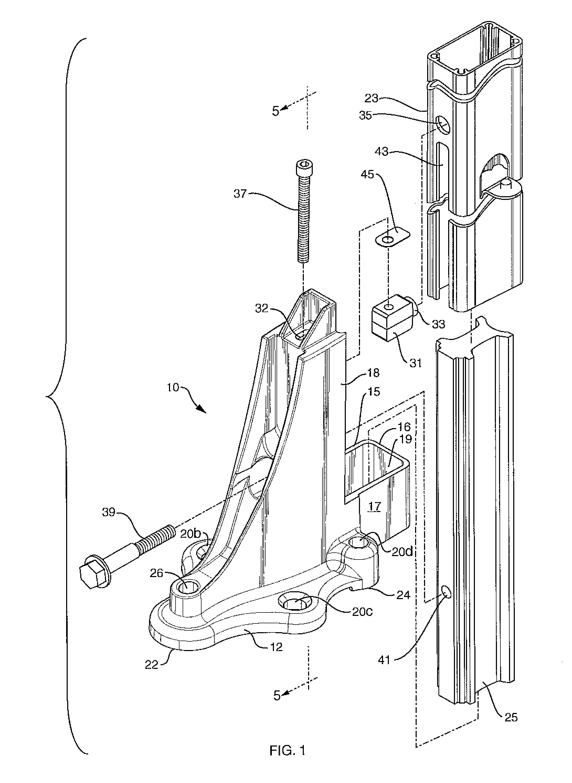
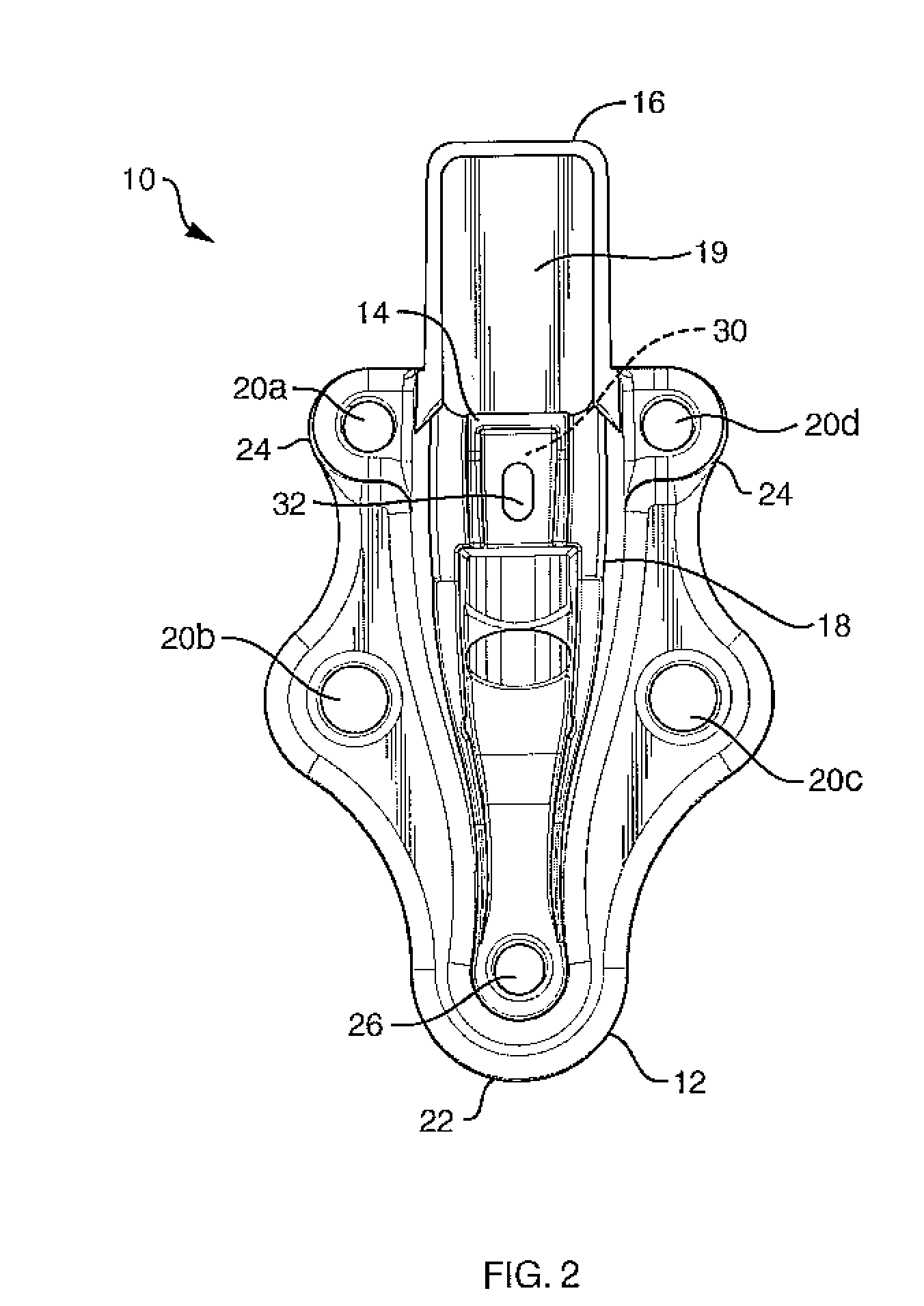
[0017]A rail post bracket 10, FIGS. 1-5, according to the preferred embodiment of present invention, is preferably made at least partially from a relatively rigid metal, such as aluminum, with sufficient strength to hold a rail post. Bracket 10 is composed of a base 12 and an upright member 18 extending up perpendicularly from base 12. Upright member 18, back longitudinal member 16, and two side longitudinal members 15 and 17 form a square or rectangular surround to hold a rail post 23 that is inserted over a rail post support 25 in the central region 19 formed by the longitudinal members. Longitudinal members 15, 17, and 16 abut each other to form the corners of the square or rectangular surround.

[0018]In the preferred embodiment, the upright member 18 is the tallest of the longitudinal members, while the side longitudinal members 15, 16 and 17 are shorter.

[0019]Base 12 preferably includes five bolt holes 20a-20d and 26. Bolts inserted into bolt holes 20a, 20d and 26 are for leveli...


PUM


Abstract

A rail post bracket includes a base with longitudinal members extending up from the base creating a square or rectangular surround for insertion of a rail post support and a rail post. The rail post support is inserted first following which the rail posts can be inserted over the rail post support and removed from the bracket to avoid the need for securing the rail posts into place using grout or concrete. The bracket base is attachable to any solid surface using bolts placed through bolt holes located in the base. Attached to the bottom of the base are adjustable feet for leveling of the rail post bracket. An adjustable mechanism is attached to and partially inset in the front longitudinal member to assist in leveling the rail post. Together these features enable a rail to be leveled in every direction and can be adjusted over time if the mounting surface moves and settles, as well as enabling the easy removal and replacement of rail posts.

Description

CROSS REFERENCE TO RELATED APPLICATION[0001]This application claims priority to U.S. Patent Application No. 60 / 975,057 filed on Sep. 25, 2007 entitled “Adjustable Railing Rail Post Bracket”, which is incorporated fully herein by reference.TECHNICAL FIELD[0002]The present invention relates to an adjustable rail post bracket for use in constructing a safety rail for balconies, porches, decks and the like and more particularly, relates to a rail post bracket having multiple adjustable feet and an adjustable wedge to level the rail post bracket and attached rail post.BACKGROUND INFORMATION[0003]Many different types of rail post brackets have been used to secure a rail post to its intended surface. Initially rail post brackets were secured in concrete filled holes. In addition to securing rail post brackets in cement filled holes later methods also included filling the base of the rail post bracket with cement to more securely hold the rail post bracket in place. However, these methods p...

Claims


Application Information

Patent Timeline
Patent Type & Authority Patents(United States)
IPC IPC(8): E04H17/22
CPCE04F11/1812Y10T403/4681E04F2011/1885E04F11/1814E04F2011/1889F16B2200/403
Inventor BEGIN, REJEAN
Owner ALUSPEK PRODS
Learn More