
Distributed base station system and method for networking thereof and base band unit

a technology of base station and network, applied in the field of base station technology, can solve the problems of high backup cost and complicated backup action, complicated network and management of system, high power consumption and cost, etc., and achieve the effect of enhancing the operational reliability of the base station system, reducing the operational cost, and small floor spa

Active Publication Date: 2011-05-03
HUAWEI TECH CO LTD
View PDF28 Cites 34 Cited by
  • Summary
  • Abstract
  • Description
  • Claims
  • Application Information

AI Technical Summary

Benefits of technology

[0010]A distributed base station system has advantages of reducing space occupancy, deducing operational cost and improving operational reliability of base station system according to the embodiments of the invention.
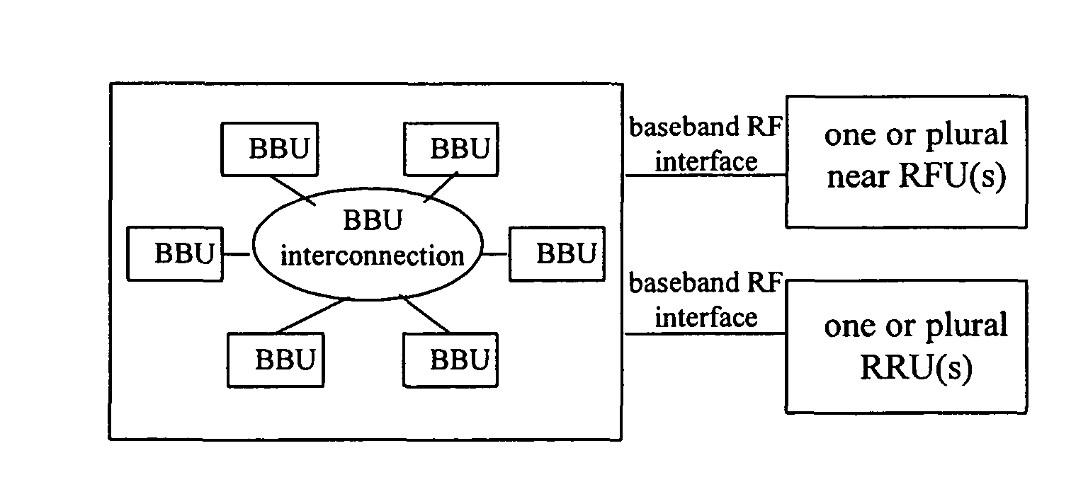
[0056]In view of the above technical solutions, in the distributed base station system in accordance with embodiments of the present invention, the base band part is separated from the RF part. The base band unit (BBU) consisting of the base band part and the RF unit (RFU) consisting of the RF part are connected to each other via base band RF interfaces. Base band units are connected to each other via capacity expansion interfaces to achieve capacity expansion in many flexible ways. In this manner, the distributed base station system should take up smaller floorage, lower the operational cost and simultaneously enhance the operational reliability of the base station system.
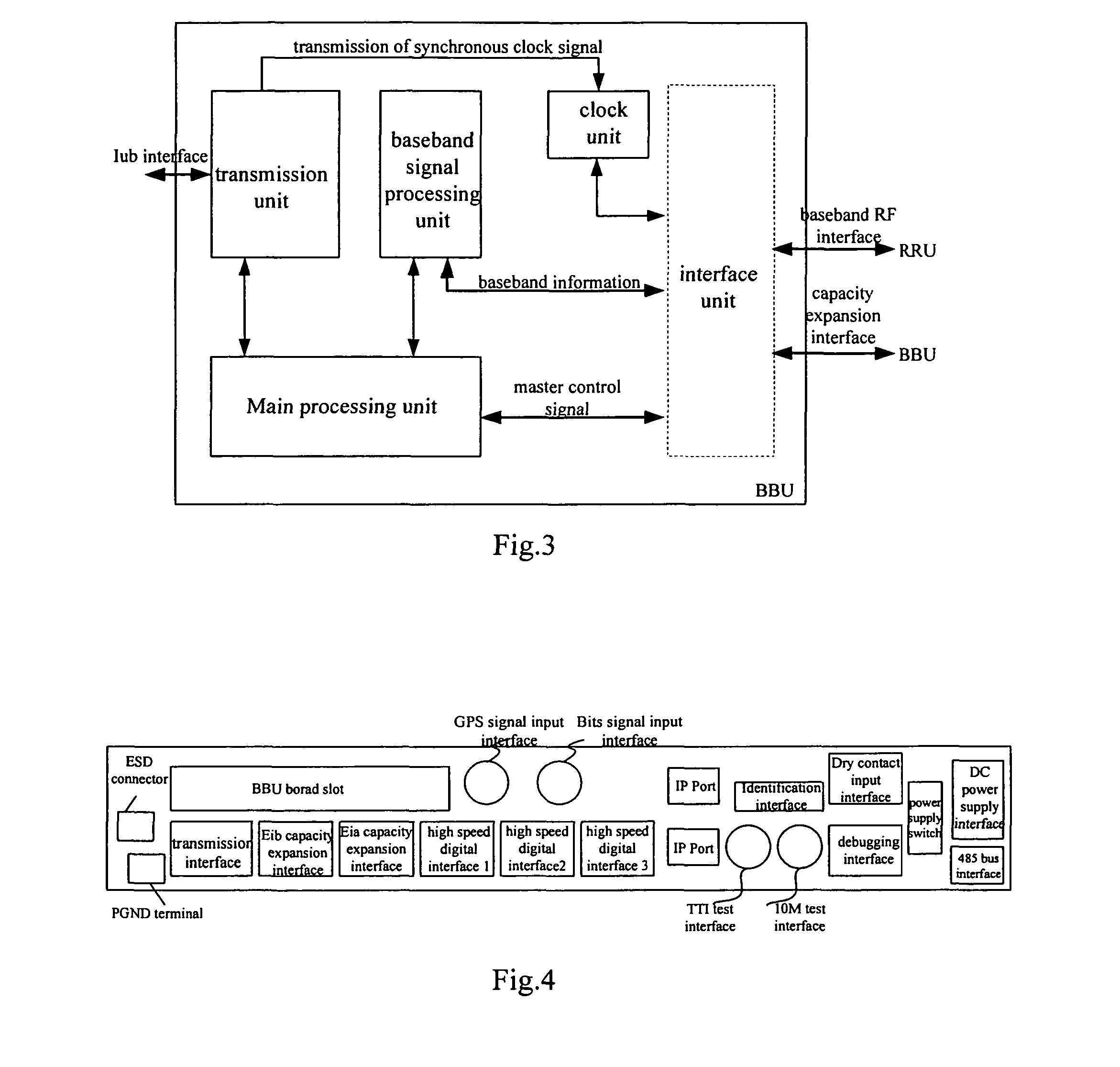
[0057]On the basis of separated arrangement of the base band unit and the RF unit, the base band unit in accordance with embodiments of the present invention is further divided to several called base band capacity units which have basic capacity according to the capacity. The basic base band capacity unit may be separated to each other so that each of the basic base band capacity unit can support the minimum configuration of base station capacity respectively, and the BBU can support macro base station capacity while combining a plurality of basic base band capacity unit together. According to the present invention, all the units in the BBU, including the transmission unit, the Main Processing & Timing unit, the base band signal processor unit and the interface unit, for example, are integrated on a single board which is 1 U high or even lower than 1 U. Then place the single board in an independent BBU box, thus reducing the size and weight of the BBU. Therefore, according to the actual needs, the BBU in the present invention can be installed freely in a standard cabinet with space being 19-inch wide and 1 U or higher than 1 U, in macro base station transmission device cabin or in other non-standard installation spaces. And distributed installation of the plurality of BBUs can be achieved with cable connection. That means that any cabinet may house the BBU in accordance with embodiments of the present invention as long as the cabinet has 1 U high spare space, thereby more flexible, more practical, and lower installation and service cost. Difficulties to find new station sites and expensive rent for station sites may be avoid, due to using the empty space of the existing stations.
[0058]Additionally, in accordance with embodiments of the present invention, the base band RF interface for connecting the BBU to the RFU and the capacity expansion interface for achieving the fully-connected topology of the BBU are set in the interface unit of the BBU. Through base band RF interfaces, BBUs and RFUs can accomplish data intercommunication and achieve a plurality of networking modes for the base station, such as a ring networking, a star networking, and a chain networking; through capacity expansion interfaces, BBUs can achieve self-cascading and BBU backup. Thus, it not only solves small capacity of mini BBU, and ensures timely expansion of the BBU capacity according to actual application needs, but also enhances flexibility for the BBU capacity expansion and new business features expansion, and lowers cost as well. Meanwhile, setting master and standby BBUs also can improve operational reliability of the base station.

Problems solved by technology

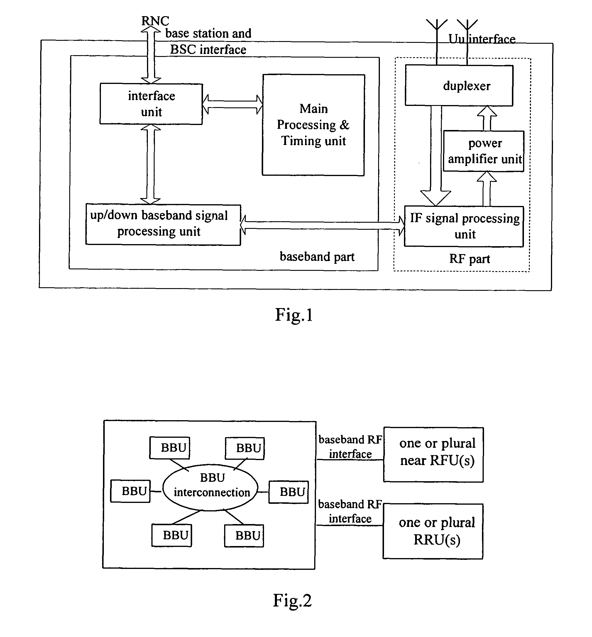
(1) In the macro base station, the transmission unit, the Main Processing & Timing unit and the uplink / downlink base band signal processing unit forming the base band part are respectively placed on different functional single boards, which are connected with one another by a backboard. Different single boards or modules may be added according to different capacity expansion requirements; the duplexer, the power amplifier unit, the IF signal processing unit that form the RF part are also placed on different functional single boards, which are connected with each other by a backboard or external wirings. All the above units are configured in one indoor or outdoor cabinet. An outdoor cabinet additionally includes such functional units as temperature control equipment, power supply, environment monitoring equipment and transmission equipment. With all the components in large sizes, the cabinet is very large and heavy, resulting in high cost of transportation and installation and a hard installation site selection, thereby, the network construction speed is badly affected. This kind of structure takes up a large space and leads to a high power consumption and cost. When backup is required, it needs to add some single boards or modules to achieve backup, thereby resulting in high backup cost and complicating backup action.
(2) In the mini base station, all the units in FIG. 1 are placed in a compact structural member module, thereby a mini base station having a small size and an easy installation. A mini base station generally supports configuration of 1-3 sectors. In the situation that one single cabinet supports one sector, a plurality of mini base stations are necessary for networking when more sectors should be supported or large capacity configuration is needed, thereby complicating networking and management of the system.
Therefore, mini base stations are not fit for the expected applications of large capacity, furthermore, are not in favor of expanding capacity of the base band part or the RF part respectively due to the base band part and the RF part adopting integration design.

Method used


Image

  • Distributed base station system and method for networking thereof and base band unit
  • Distributed base station system and method for networking thereof and base band unit
  • Distributed base station system and method for networking thereof and base band unit

Examples


first embodiment

[0116]FIG. 8 (a) is a schematic diagram illustrating the network structure with one BBU and three RRUs. As shown in FIG. 8 (a), one BBU and three RRUs are connected respectively via a base band RF interface. Each of the RRUs belongs to a sector, and each of the RRUs adopts a networking configuration with single carrier wave. That is, the networking mode illustrated in FIG. 8 (a) supports networking of 3×1 configuration, in which 3 refers to 3 sectors, and 1 means single carrier wave.

second embodiment

[0117]FIG. 8 (b) is a schematic diagram illustrating network structure with two BBUs and three RRUs in the present invention. As shown in FIG. 8 (b), the BBU1 and the RRU2 are connected via an Eia capacity expansion interface to form network with master-standby relationship. The BBU1 and the BBU2 are connected with three RRUs respectively via three base band RF interfaces respectively, each of the RRUs belongs to a sector, and each of the RRUs adopts a networking configuration with single carrier wave backup. That is, the networking mode illustrated in FIG. 8 (b) supports networking of 3×1 configuration, in which 3 refers to 3 sectors, and 1 means single carrier wave. Suppose that the slot position label of the BBU1 is preset as a master BBU identifier, and the slot position label of the BBU2 is preset as a standby BBU identifier, then, the operation principles of the networking in FIG. 8 (b) are described as follows. After accomplishing the networking as illustrated in FIG. 8 (b), ...

third embodiment

[0119]FIG. 8 (c) is a schematic diagram illustrating network structure with two BBUs and three RRUs. As shown in FIG. 8 (b), the BBU1 and the RRU2 are connected via an Eib capacity expansion interface and form a network with master-slave relationship. The BBU1 are connected with three RRUs respectively via three base band RF interfaces. Each of the RRUs belongs to a sector, and each of the RRUs adopts a network configuration with two-carrier wave. That is, the networking mode illustrated in FIG. 8 (c) supports networking of 3×2 configuration, in which, 3 refers to 3 sectors, and 2 means 2 carrier waves. Since the BBU1 and the BBU2 have a master-slave relationship, the BBU uplink / downlink data capacity is increased to twice of that when a single BBU is used.

[0120]The operation principles of networking illustrated in FIG. 8 (c) are completely the same as those in FIG. 8 (b). The difference between them is in that in FIG. 8 (c), failure of the BBU1 is only reported to the RNC with no b...


PUM


Abstract

The present invention discloses a distributed base station system as well as its networking method and base band unit. In this system, the base band unit (BBU) and RF unit (RFU) of the base station are separated, and the RFU is equipped with base band RF interfaces for interconnecting the BBU and transmitting data information, thereby forming the base station. Based on the separation of the BBU from the RFU, the BBU capacity is further divided at the same time, and every unit is also arranged independently. The BBU networking and capacity expansion may be achieved with capacity expansion interfaces and base band RF interfaces provided by BBU interface units in flexible and convenient ways.

Description

FIELD OF THE TECHNOLOGY[0001]The present invention relates to the base station technology, and more specifically to a distributed base station system and a method for networking thereof and base band units forming the distributed base station.BACKGROUND OF THE INVENTION[0002]In mobile communication systems, base stations are important components used for connecting User terminals to Base Station Controllers (BSC), receiving and transmitting radio signals between the User terminals and the BSCs, thereby conducting User terminals to access wireless networks and simultaneously accomplishing information intercommunications between User terminals and the BSCs. As shown in FIG. 1, a base station includes:[0003]a Base Station &BSC interface unit, also called transmission unit, used for accomplishing interface functions between the base station and the BSC; a Main Processing & Timing unit, on the one hand, for controlling the base station and exchanging cell and traffic data among the units...

Claims


Application Information

Patent Timeline
Patent Type & Authority Patents(United States)
IPC IPC(8): H04M1/00H04W88/08H04W88/14
CPCH04W88/08
Inventor WU, WANGJUNYU, CHENGDONGTAN, ZHUPU, TAOHE, WENSHENGLAN, PENGZHOU, JUNYU, MING
Owner HUAWEI TECH CO LTD
Learn More