
Shorthand connection identifier with embedded subfield

a technology of shorthand connection and subfield, applied in connection management, wireless commuication services, power management, etc., can solve the problem that the performance improvement of wireless communication systems should not be compared to the obsolete legacy equipmen

Inactive Publication Date: 2011-05-03
MONUMENT BANK OF INTPROP LLC
View PDF5 Cites 6 Cited by
  • Summary
  • Abstract
  • Description
  • Claims
  • Application Information

AI Technical Summary

Benefits of technology

This approach enables increased data transfer rates while ensuring compatibility with legacy equipment, allowing for efficient communication of control information and other data without rendering older devices obsolete, thus enhancing the flexibility and performance of wireless communication systems.

Problems solved by technology

However, improvements in the performance of the wireless communication systems should not operate to obsolete legacy equipment that may still serve the needs of a significant component of the users.

Method used


Image

  • Shorthand connection identifier with embedded subfield
  • Shorthand connection identifier with embedded subfield
  • Shorthand connection identifier with embedded subfield

Examples


Embodiment Construction

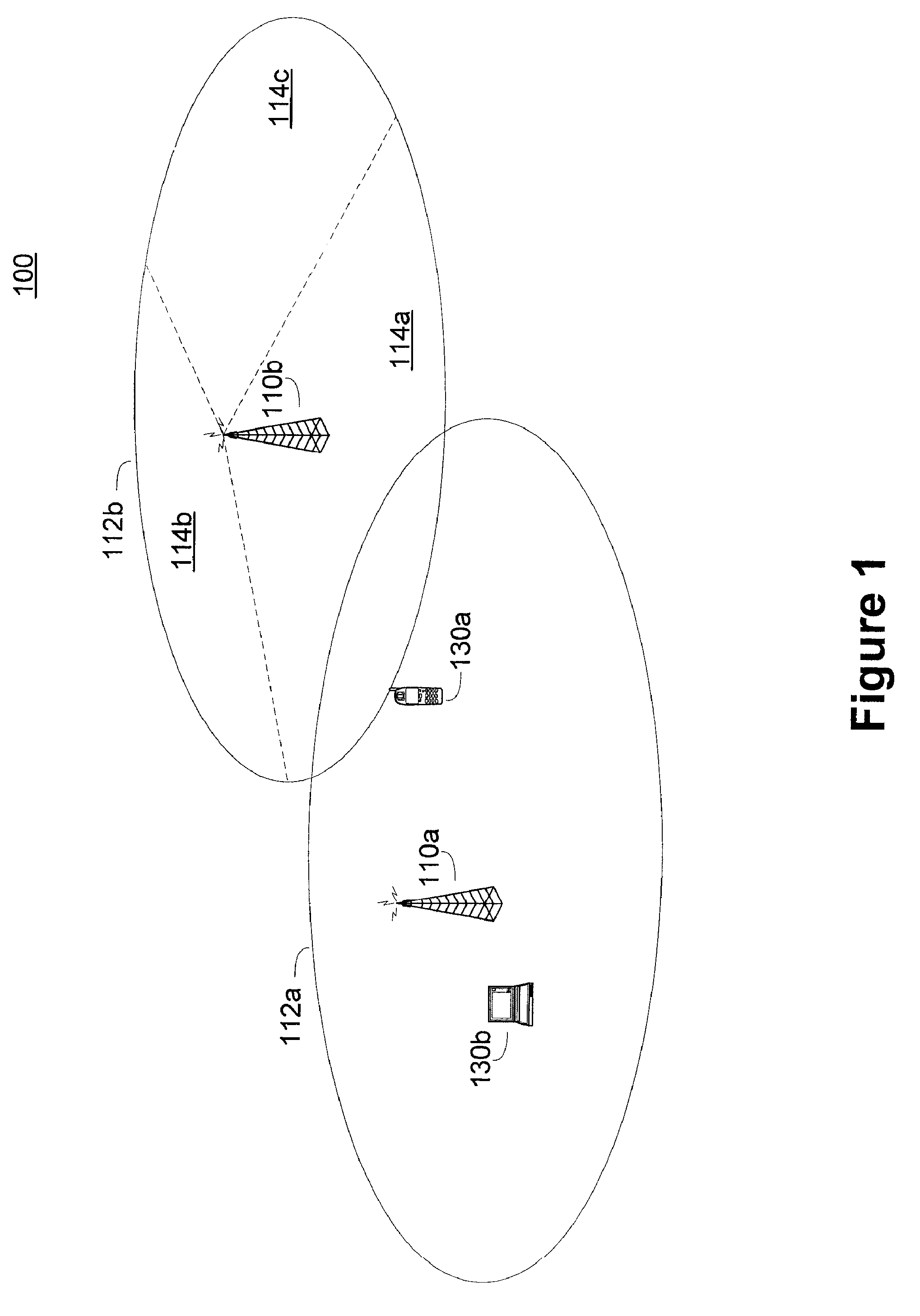
[0023]FIG. 1 is a simplified functional block diagram of an embodiment of a wireless communication system 100. The wireless communication system 100 includes a plurality of base stations 110a, 110b, each supporting a corresponding service or coverage area 112a, 112b. Each base station 110a and 110b can be coupled to a network (not shown) such as a wired network, and can be configured to allow wireless communication with devices on the wired network.

[0024]A base station, for example 110a, can communicate with wireless devices within its coverage area 112a. For example, the first base station 110a can wirelessly communicate with a first subscriber station 130a and a second subscriber station 130b within the coverage area 112a. In another example, the first subscriber station 130a can communicate with a remote device (not shown) via the first base station 110a. In another example, the first subscriber station 130a can communicate with the second subscriber station 130b via the first ba...


PUM


Abstract

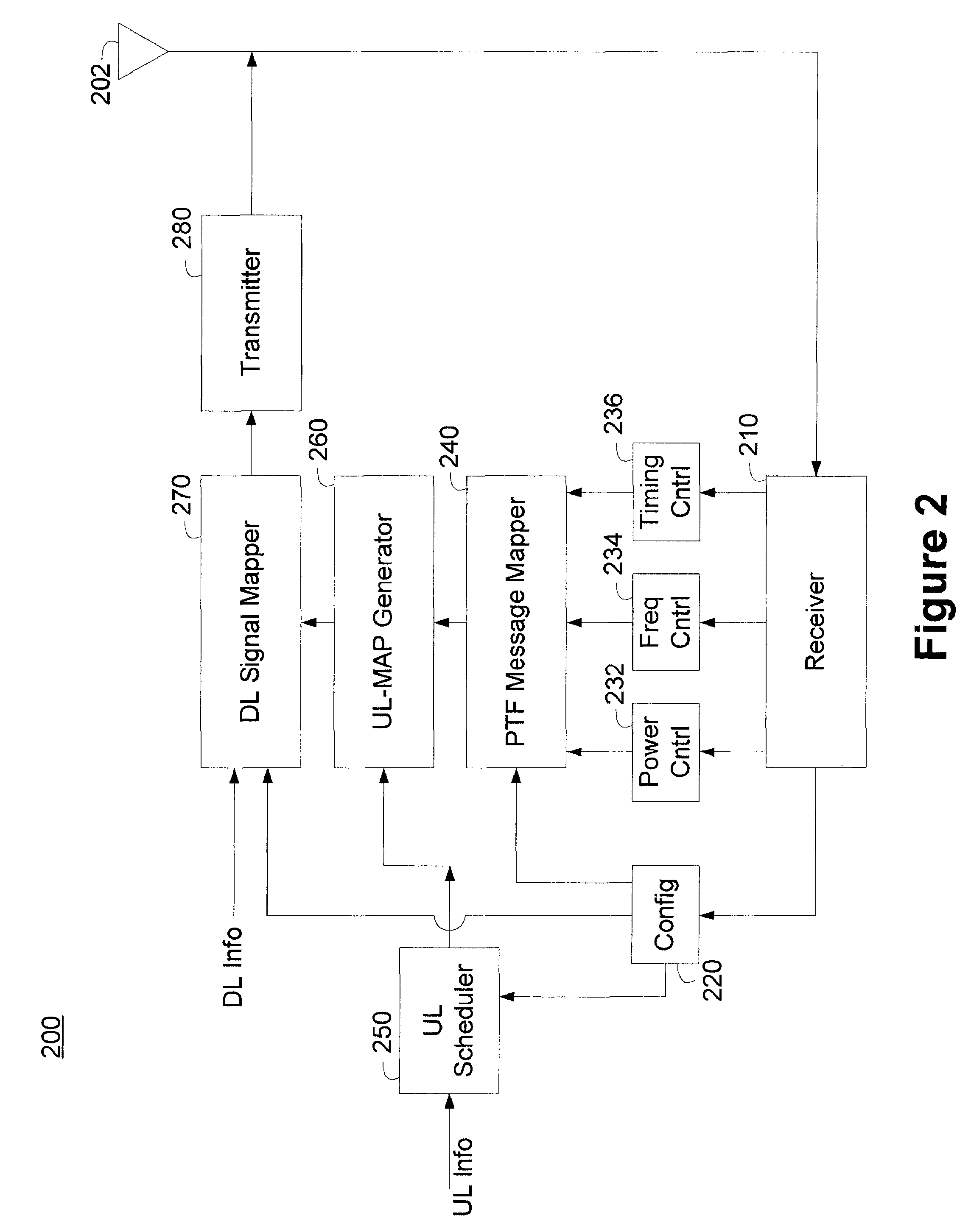
A base station can communicate resource allocation to a wireless mobile station in an uplink map information element. The base station can identify destination mobile stations using a shorthand connection identifier. The base station parses the connection identifier field into a shorthand connection identifier field and an embedded subfield data field. The shorthand connection identifier field can be sized to support a predetermined number of mobile stations. The base station can further parse the embedded subfield field into a number of sub-fields, each communicating a different set of control information. In one embodiment, the base station utilizes the embedded subfield to communicate power, timing, and frequency information to the destination mobile station.

Description

BACKGROUND OF THE INVENTION[0001]Wireless communication systems are under constant pressure to support increased data transfer rates. The desire to increase data rates often accompanies the desire to operate wireless communication devices in non-ideal environments, including mobile environments. The wireless communication systems often incorporate more complex hardware constraints in an attempt to maximize the bandwidth available for communications.[0002]The design of wireless communication systems need to be flexible so that they can accommodate users and devices as technology, and the needs of users, change over time. However, improvements in the performance of the wireless communication systems should not operate to obsolete legacy equipment that may still serve the needs of a significant component of the users.[0003]Thus, it is desirable to increase the information that can be communicated in a wireless communication system, but the increased ability to communicate information s...

Claims


Application Information

Patent Timeline
Patent Type & Authority Patents(United States)
IPC IPC(8): H04W72/00H04W8/26H04W28/06H04W52/08H04W72/14
CPCH04W72/1289H04W52/08H04W76/021H04W76/11H04W72/23
Inventor BOURLAS, YAIRSUTTON, TODDGUMMADI, SRIKANTHWANG, LEI
Owner MONUMENT BANK OF INTPROP LLC
Learn More