Low emission natural gas processing dehydration system

a technology of natural gas processing and low emission, which is applied in the direction of liquid degasification, domestic cooling apparatus, separation processes, etc., can solve the problems of inability to release hydrocarbons into the environment, and achieve the effect of significantly limiting the formation of nitrogen oxides and reducing the amount of fuel gas required

Active Publication Date: 2011-05-03
PROCESS EQUIP & SERVICE
View PDF8 Cites 5 Cited by
  • Summary
  • Abstract
  • Description
  • Claims
  • Application Information

AI Technical Summary

Benefits of technology

[0017]Non-condensible vapors and water along with the absorbed hydrocarbons exit the condensate separator and are conveyed, utilizing natural draft forces and gravity, to a vaporization chamber immersed in hot glycol in the reboiler. In the vaporization chamber, the water is re-vaporized into steam and mixes with the non-condensible vapors. All of the hydrocarbons present, including those previously entrained in the water, are combusted in the firetube of the reboiler and also result in a significant reduction of fuel gas required for the reboiler.
[0018]Steam induction into the combustion zone of the firetube also cools the combustion process, thereby significantly limiting formation of nitrogen oxides.

Problems solved by technology

Increasingly, it is unacceptable to release hydrocarbons into the environment.
Choi (U.S. Pat. No. 5,163,981) proposes controlling discharge of pollutants from natural gas dehydrators, however, water and entrained hydrocarbon gas is simply separated out by the system and requires proper disposal.

Method used


Image

  • Low emission natural gas processing dehydration system
  • Low emission natural gas processing dehydration system

Examples


Embodiment Construction

[0020]The embodiments discussed herein are merely illustrative of specific manners in which to make and use the invention and are not to be interpreted as limiting the scope of the instant invention.

[0021]While the invention has been described with a certain degree of particularity, it is to be noted that many modifications may be made in the details of the invention's construction and the arrangement of its components without departing from the spirit and scope of this disclosure. It is understood that the invention is not limited to the embodiments set forth herein for purposes of exemplification.

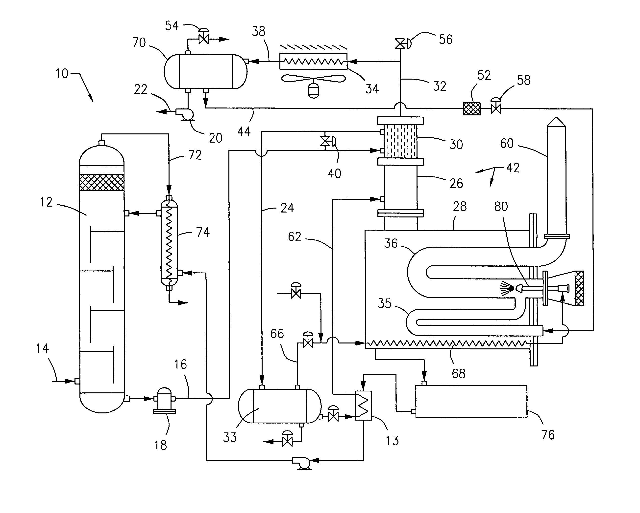
[0022]FIG. 1 is a schematic diagram or illustration of a low emission natural gas processing dehydration system 10. A known contactor tower 12 is utilized in which produced natural gas delivered to the surface is directed through an inlet 14 and is contacted with a liquid desiccant, such as glycol, for removal of water and water vapor. The glycol may be passed in counter current with the ...


PUM

PropertyMeasurementUnit
gravityaaaaaaaaaa
corrosionaaaaaaaaaa
temperatureaaaaaaaaaa

Abstract

A process to reduce emissions discharged from a natural gas processing system wherein the processing system includes a glycol dehydrator for absorbing water, moisture and absorbable hydrocarbons, a reboiler for heating water rich glycol, a still column in communication with the reboiler and a reflux condenser. The process includes the steps of directing vapors and gases from the still column and reflux condenser to a condenser in order to condense vapors to liquid. The gases and liquids from the condenser are directed to a condensate separator in order to separate by gravity. Non-condensible vapors and water from the condensate separator are delivered to a vaporization chamber immersed in the reboiler. Water is re-vaporized into steam and permitted to mix with non-condensible vapors in the vaporization chamber. The steam and non-condensible vapors are inducted into a combustion zone in a firetube in the reboiler. The hydrocarbons in the vapors are combusted in the firetube.

Description

BACKGROUND OF THE INVENTION[0001]1. Field of the Invention[0002]The present invention relates to a process to reduce emissions discharge from a natural gas processing dehydration system. In particular, the invention relates to a self-contained natural gas processing system which eliminates discharge of gaseous hydrocarbons to the environment.[0003]2. Prior Art[0004]Natural gas processing systems are used to treat and purify raw natural gas that is obtained from subterranean locations and delivered to the surface. The treated natural gas is used in a wide variety of fuel applications.[0005]The natural gas delivered to the surface contains primarily methane but also includes aromatic and other gaseous hydrocarbons including ethane, propane; butane, and pentanes, as well as carbon dioxide, hydrogen sulfide, mercaptans, nitrogen, water, water vapor, and liquid hydrocarbons, such as crude oil.[0006]It is common practice and is necessary to process or condition the natural gas in the fiel...

Claims


Application Information

Patent Timeline
Patent Type & Authority Patents(United States)
IPC IPC(8): B01D3/06F25J3/06B01D19/00
CPCC10L3/10B01D19/0036Y10S203/11
Inventor RHODES, JAMES E.
Owner PROCESS EQUIP & SERVICE
Why Eureka
Try Eureka