
QAM symbol slicing method and apparatus

a symbol slicing and symbol technology, applied in the field of symbols slicing and symbol slicing methods, can solve the problems of increasing complexity, aggravating hardware implementation difficulties, and reducing the scalability of conventional qam slicers, so as to reduce the hardware complexity of qam digital demodulators and increase or decrease the order of qam modulation

Inactive Publication Date: 2011-04-26
ELECTRONICS & TELECOMM RES INST
View PDF4 Cites 0 Cited by
  • Summary
  • Abstract
  • Description
  • Claims
  • Application Information

AI Technical Summary

Benefits of technology

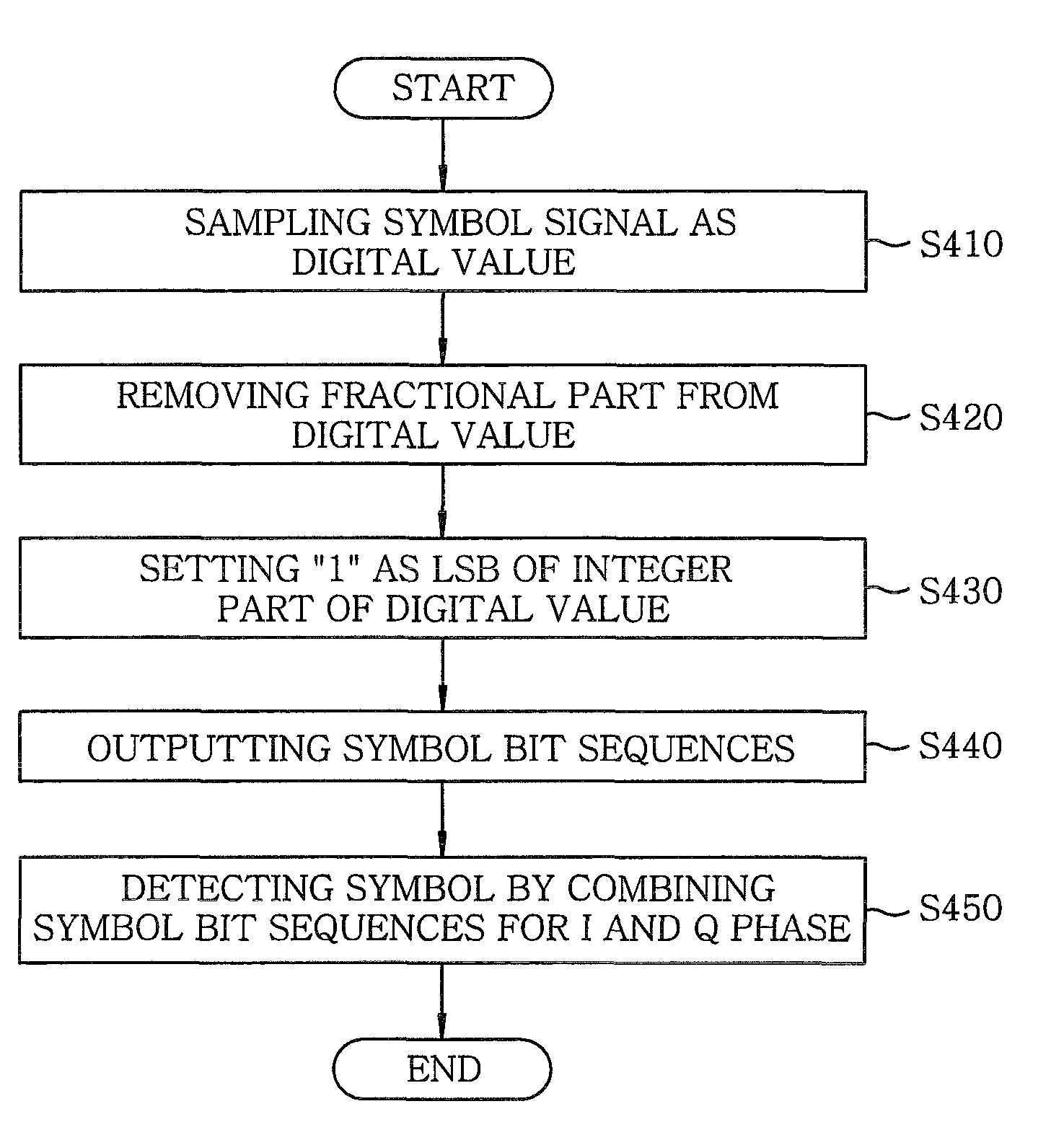
The present invention provides a method and apparatus for extracting a symbol bit sequence in a QAM digital demodulator. This method can reduce the hardware complexity of the demodulator and is applicable even if the order of QAM modulation is increased or decreased. The method involves acquiring a digital value by sampling a symbol signal and extracting the symbol bit sequence from the digital value using an LSB of an integer value. The LSB is set to a predetermined value that stands for a region where the digital value belongs. The method also involves combining bits of the digital value except for the LSB with a resulting value of a logical OR operation between the LSB and an inverted value of the LSB to output the symbol bit sequence. This method can be implemented using a symbol slicer that includes digital sampling units and a symbol bit sequence extracting unit.

Problems solved by technology

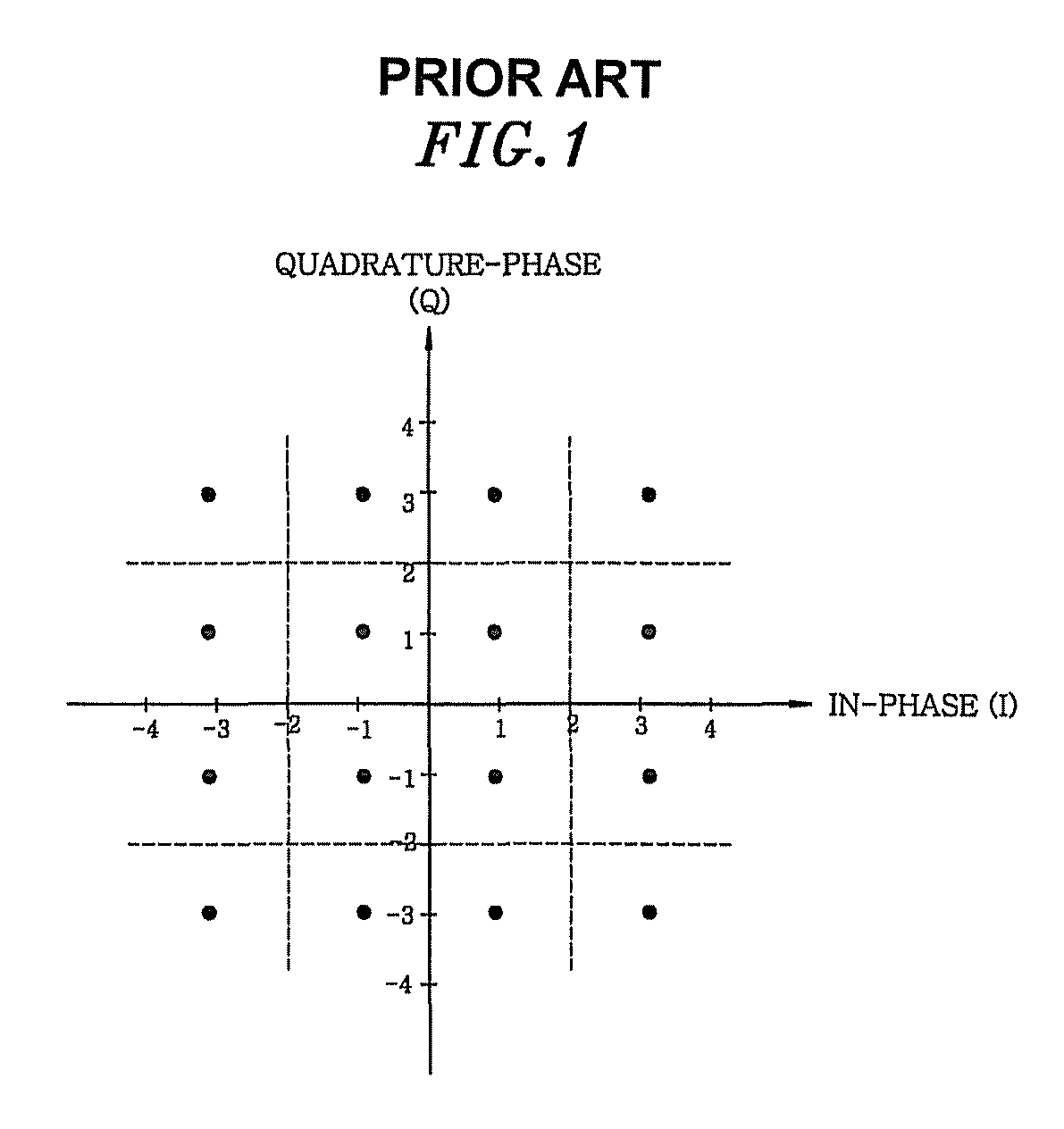
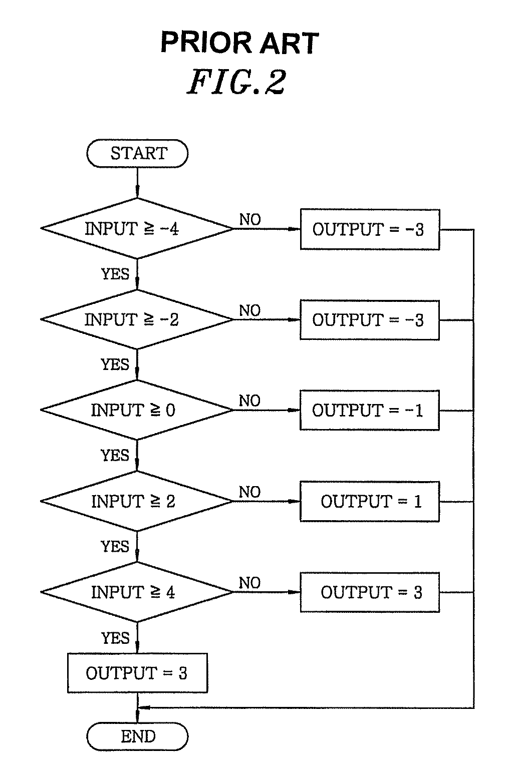
However, the above method of bit sequence extraction by the conventional QAM slicer has a drawback of a high hardware complexity, because, for identifying a single symbol, the I and Q components thereof need to be compared to a plurality of boundary values.
Specifically, when the order of QAM modulation increases as 64, 256 and 1024, the number of boundary values to be compared increases greatly, thereby increasing the complexity and aggravating a difficulty in the implementation of the hardware.
In addition to this, the conventional QAM slicer is limited in scalability in that, in accordance with the conventional method, a slicer structure used for a 128QAM scheme cannot be applied to a 256QAM scheme for example.

Method used


Image

  • QAM symbol slicing method and apparatus
  • QAM symbol slicing method and apparatus
  • QAM symbol slicing method and apparatus

Examples


Embodiment Construction

[0022]Hereinafter, embodiments of the present invention will be described in detail with reference to the accompanying drawings, which forms a part hereof. For convenience, the following description will be made on the basis of a 16QAM symbol signal with a signal constellation shown in FIG. 1. However, it should be apparent to those skilled in the art that the scope of the present invention is not limited thereto.

[0023]FIG. 3 is a diagram for illustrating digital expressions of the I or Q coordinate in the signal constellation in accordance with an embodiment of the present invention.

[0024]As shown therein, the I or Q coordinate in the signal constellation has determination regions for respective symbols. In specific, if a coordinate of a symbol signal belongs to a region 310 in the I or Q axis, a symbol slicer in accordance with the present embodiment of the invention determines that a representative bit sequence of the symbol signal is “101b” Likewise, the symbol slicer extracts r...


PUM


Abstract

A method for slicing a symbol in a QAM digital demodulator, includes acquiring a digital integer value by sampling a symbol signal in an in-phase coordinate or a quadrature-phase coordinate; and extracting a symbol bit sequence in the in-phase coordinate or the quadrature-phase coordinate from a whole bit sequence of the digital integer value by using an LSB thereof. Further, a symbol slicer for detecting a QAM symbol, includes digital sampling units, each of which acquires a digital integer value by sampling a symbol signal in an in-phase coordinate or a quadrature-phase coordinate; and a symbol bit sequence extracting unit that extracts a symbol bit sequence in the in-phase coordinate or the quadrature-phase coordinate from a whole bit sequence of the digital integer value by using an LSB thereof.

Description

[0001]This application is a continuation application of PCT international application serial number PCT / KR2007 / 006135 filed on Nov. 30, 2007, which is designated the United States.CROSS-REFERENCE(S) TO RELATED APPLICATION(S)[0002]The present invention claims priority of Korean Patent Application No. 10-2006-0124289, filed on Dec. 8, 2006, and Korean Patent Application No. 10-2007-0035521, filed on Apr. 11, 2007, which are incorporated herein by references.FIELD OF THE INVENTION[0003]The present invention relates to a digital demodulator and a method of detecting a digital signal; and more particularly, to a symbol slicer and symbol slicing method for use in a Quadrature Amplitude Modulation (QAM) scheme.BACKGROUND OF THE INVENTION[0004]“Quadrature Amplitude Modulation (QAM)” refers to a kind of digital modulation scheme in which symbols are arranged in a lattice form with a specific interval in a signal constellation to determine a magnitude and a phase of a transmission signal, whe...

Claims


Application Information

Patent Timeline
Patent Type & Authority Patents(United States)
IPC IPC(8): H04L27/06
CPCH04L27/3881H04L27/34H04L27/32H04L27/04H04L27/02
Inventor JIN, EUN SOOKSONG, YUN JEONGLEE, SOO IN
Owner ELECTRONICS & TELECOMM RES INST
Learn More