
Method for producing an aircraft with reduced environmental impact and the aircraft thus obtained

Active Publication Date: 2011-04-19
AIRBUS OPERATIONS (SAS)
View PDF14 Cites 18 Cited by
  • Summary
  • Abstract
  • Description
  • Claims
  • Application Information

AI Technical Summary

Benefits of technology

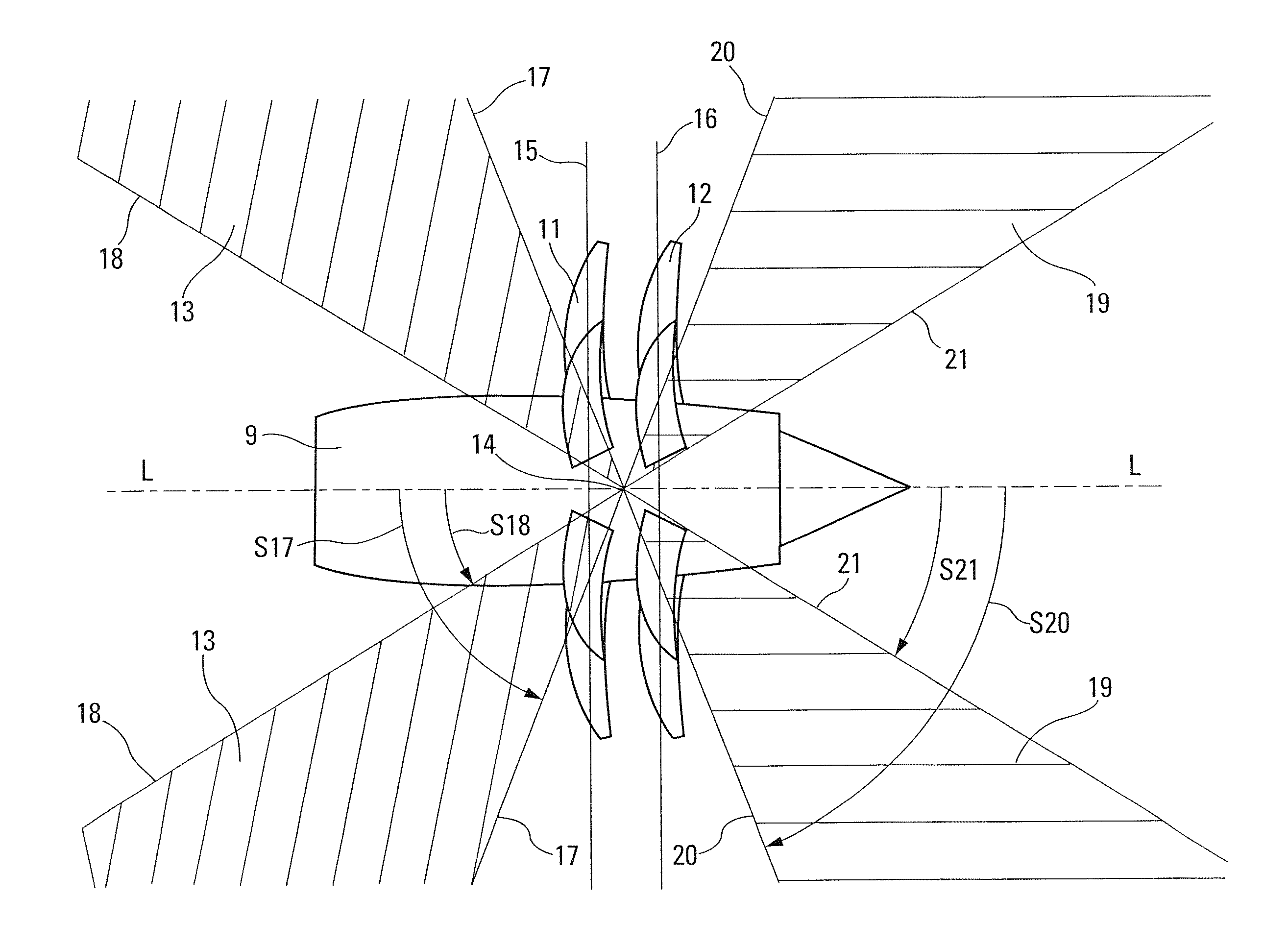
[0009]The object of the present invention is to produce an aircraft with reduced environmental impact comprising at least one turboprop with two contrarotating propellers, mounted at the rear of said aircraft, on the back of the latter, applying the principle of masking noise with portions of the airframe of said aircraft so that the noise felt beneath said aircraft, particularly during take-offs and landings, is at least partially masked.
[0021]In such an aircraft complying with the present invention, in order to allow a satisfactory masking of the propeller interaction noise corresponding to said front lobe, it is advantageous that said wings have a reverse sweep—that is to say that their free ends are further forward than their wing root sections—which makes it possible, while retaining a satisfactory quality of flight (particularly with respect to the position of the aerodynamic center relative to the center of gravity of the aircraft), to move said wing root sections sufficiently rearward for said wings, and the portion of fuselage placed between them, to be able to mask the forward noise. In addition, this reverse sweep makes it possible to limit, if not eliminate, the portions of the wings (in particular the sensitive elements such as the flaps or the fuel tanks) exposed to the risks of destruction by debris originating from the possible breakup of the turboprop. The angle of reverse sweep may be of the order of around twenty degrees.
[0023]In the aircraft according to the present invention, the two contrarotating propellers are advantageously in front of the horizontal stabilizer, so that, in the case of an uncontained breakage of a portion of the turbine and / or breakage of a portion of the propellers, debris from the latter cannot damage or destroy the horizontal stabilizer, the stabilizer strut supporting the latter, or even the vertical stabilizer(s). The aircraft according to the invention therefore is not very sensitive to a possible breakup of the turboprop, all the more so since, level with said contrarotating propellers, the fuselage can be easily reinforced.
[0027]Where necessary, in order to compensate for the impact of moving the wings rearward due to their reverse sweep on the longitudinal stability of the aircraft, a movable airfoil of the canard type, at the front of the latter, can be provided. Such a canard surface also makes it possible to compensate for the reduction of the lever arm of the horizontal stabilizer relative to the center of the airfoil which otherwise could require an excessive increase in the surface area of said horizontal stabilizer. In addition, it helps in the rotation of the aircraft on take-off.
[0029]The aircraft according to the present invention may be single-engined and comprise only one turboprop with two contrarotating propellers mounted at the rear in the manner described hereinabove. However, in addition to this single turboprop, it may also comprise at least two turboshaft engines supported symmetrically by the wings of said aircraft. Such an arrangement is advantageous in the sense that the turboprop, consuming little fuel and not being very noisy due to the anti-noise mask according to the invention, makes it possible to reduce the power (and hence the noise and fuel consumption) of the turboshaft engines.
[0031]Because of the rearward position of the wings of the aircraft according to the present invention, it is advantageous that the landing gear is beneath the fuselage in front of said wings. However, as a variant, said wings may comprise, in the vicinity of the fuselage, a forward-angled airfoil element in the concave leading edge of said wings, in order to allow the landing gear to be installed beneath the wings.

Problems solved by technology

However, most of the existing aircraft are propelled by turboshaft engines which, on the one hand, have a high fuel consumption and, on the other hand, are sources of environmental pollution via their emissions into the atmosphere.
However, in operation, turboprops are still noisier than turboshaft engines, so that the advantage in energy-saving and environmental pollution through emissions, from which benefit would be derived by replacing turboshaft engines with turboprops, would be accompanied by the disadvantage of increased noise pollution.
The noise pollution thus achieved would be unacceptable and, in any case, difficult to make compatible with the regulations that are currently in force.

Method used


Image

  • Method for producing an aircraft with reduced environmental impact and the aircraft thus obtained
  • Method for producing an aircraft with reduced environmental impact and the aircraft thus obtained
  • Method for producing an aircraft with reduced environmental impact and the aircraft thus obtained

Examples


Embodiment Construction

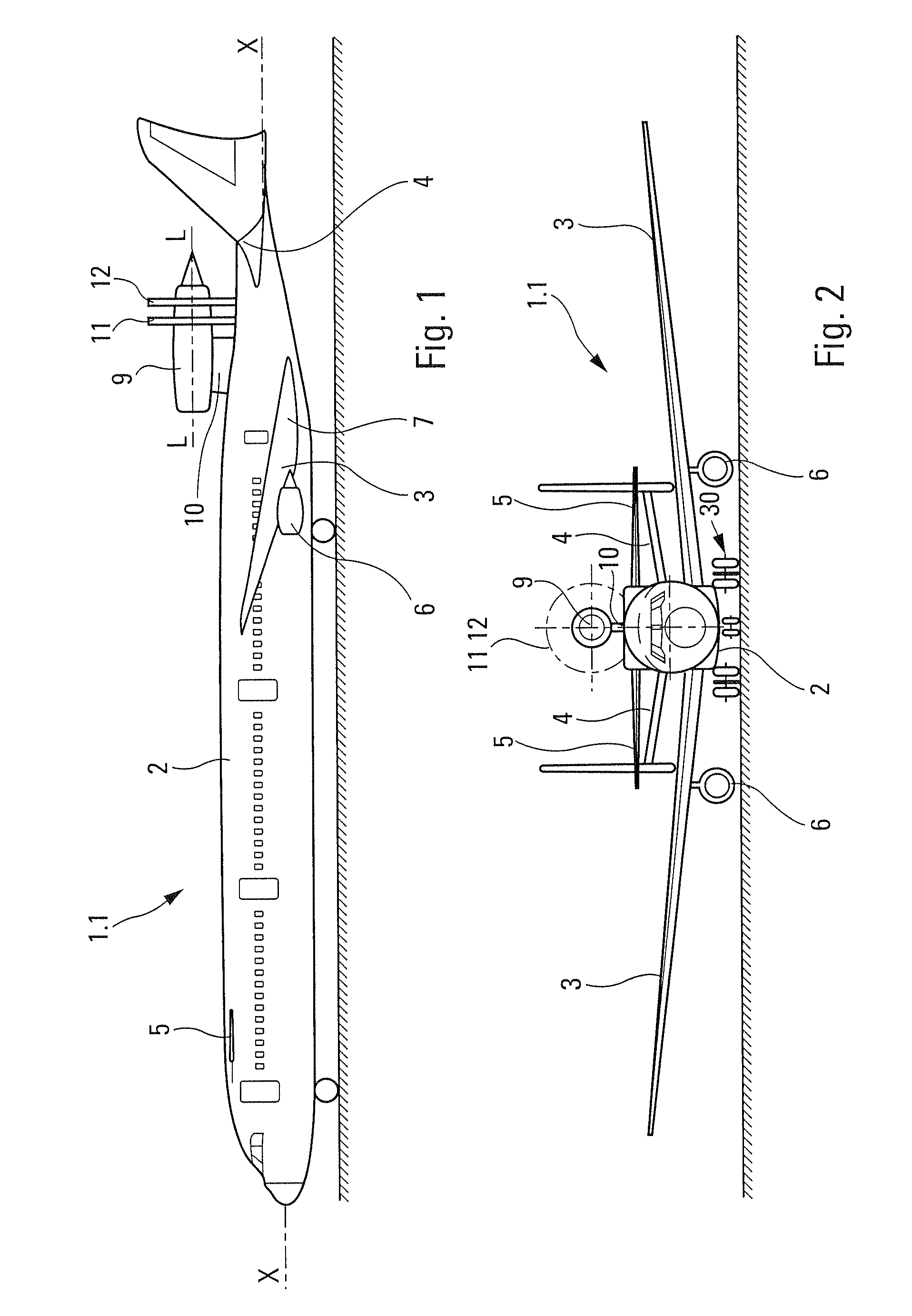
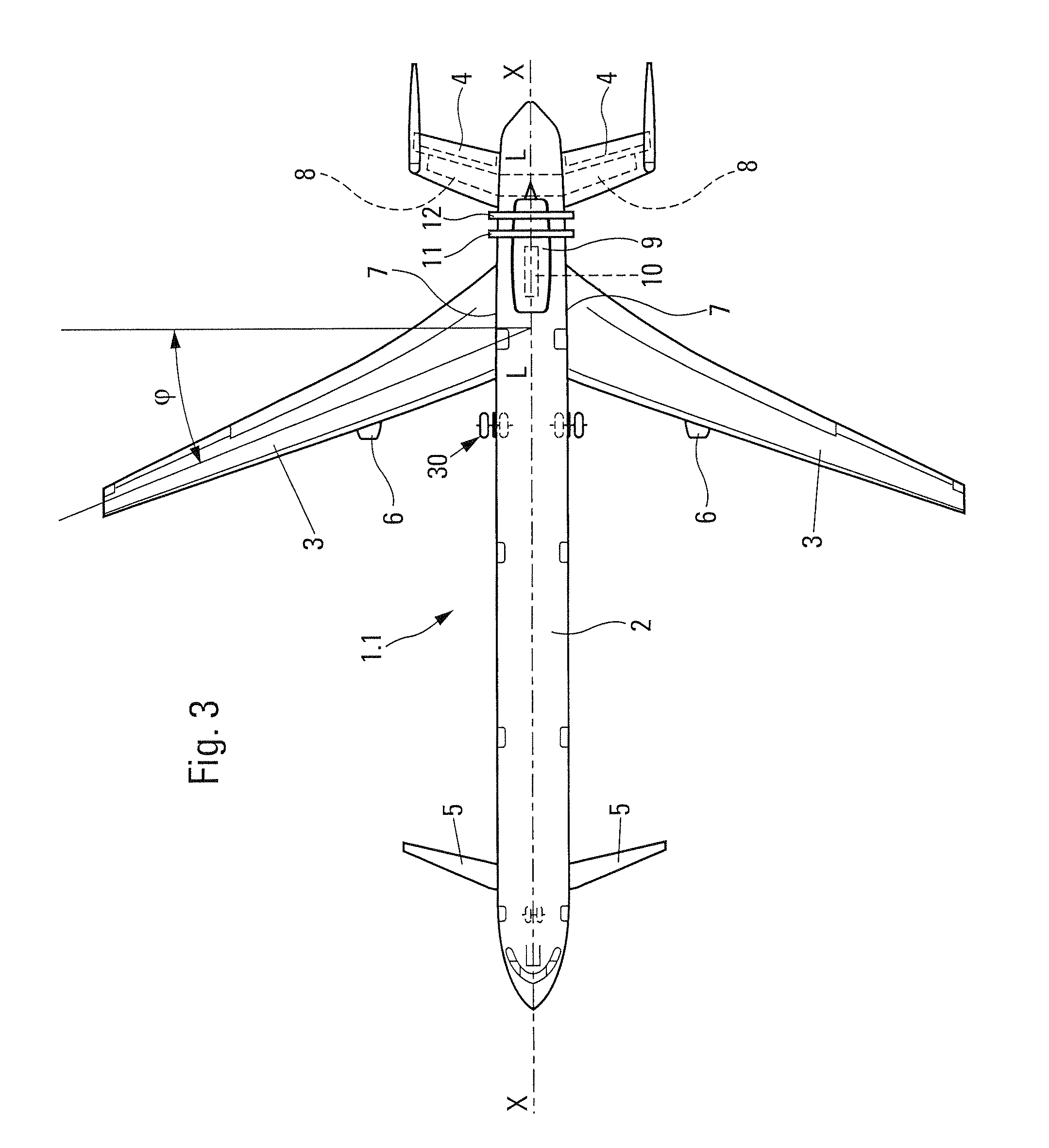
[0039]The commercial aircraft 1.1, according to the invention and shown schematically in FIGS. 1 to 3, has a longitudinal axis X-X and comprises a fuselage 2, provided with two symmetrical wings 3, a rear horizontal stabilizer 4 and a front airfoil 5 of the canard type.

[0040]The wings 3, which each support a turboshaft engine 6, have a reverse sweep Φ, for example of the order of around twenty degrees, and their wing root sections 7 are moved backward toward said horizontal stabilizer 4.

[0041]The horizontal stabilizer 4 is of the known THS type with variable inclination and is supported by a stabilizer strut 8.

[0042]On the back of the rear portion of its fuselage, the aircraft 1.1 supports a turboprop 9, supported by a vertically protruding pylon 10 fixedly attached to the structure of said aircraft. The turboprop 9 has an axis L-L parallel with the longitudinal axis X-X (the axes L-L and X-X define the vertical horizontal mid-plane of the aircraft 1.1) and comprises two unshrouded ...


PUM


Abstract

An aircraft with reduced environmental impact includes a turboprop, having two contra-rotating propellers, disposed on the rear portion on the back of the aircraft's fuselage so that the interaction noise of the propellers is masked, in the forward direction, by the wings and, in the rearward direction, by the aircraft's horizontal stabilizer.

Description

FIELD OF THE INVENTION[0001]The present invention relates to a method for producing an aircraft with reduced environmental impact and the aircraft obtained by applying this method.BACKGROUND OF THE RELATED ART[0002]It is known that turboprops, with one or more propellers, have better energy efficiencies than turboshaft engines.[0003]However, most of the existing aircraft are propelled by turboshaft engines which, on the one hand, have a high fuel consumption and, on the other hand, are sources of environmental pollution via their emissions into the atmosphere.[0004]Therefore, with respect to energy-saving and environmental pollution, it would be more advantageous to furnish aircraft with turboprops rather than with turboshaft engines.[0005]However, in operation, turboprops are still noisier than turboshaft engines, so that the advantage in energy-saving and environmental pollution through emissions, from which benefit would be derived by replacing turboshaft engines with turboprops,...

Claims


Application Information

Patent Timeline
IPC IPC(8): B64D27/00
CPCB64C3/10B64C5/06B64D27/14B64C39/12B64C11/48
Inventor GALL, PIERRE-EMMANUELRICOUARD, JULIEN
Owner AIRBUS OPERATIONS (SAS)
Learn More