
Vehicle lamp assembly

a technology for vehicle lamps and assembly parts, applied in vehicle interior lighting, transportation and packaging, light and heating equipment, etc., can solve the problem of freeing up otherwise scarce and valuable packaging space, and achieve the effect of cost saving

Inactive Publication Date: 2011-04-12
GM GLOBAL TECH OPERATIONS LLC
View PDF3 Cites 10 Cited by
  • Summary
  • Abstract
  • Description
  • Claims
  • Application Information

AI Technical Summary

Benefits of technology

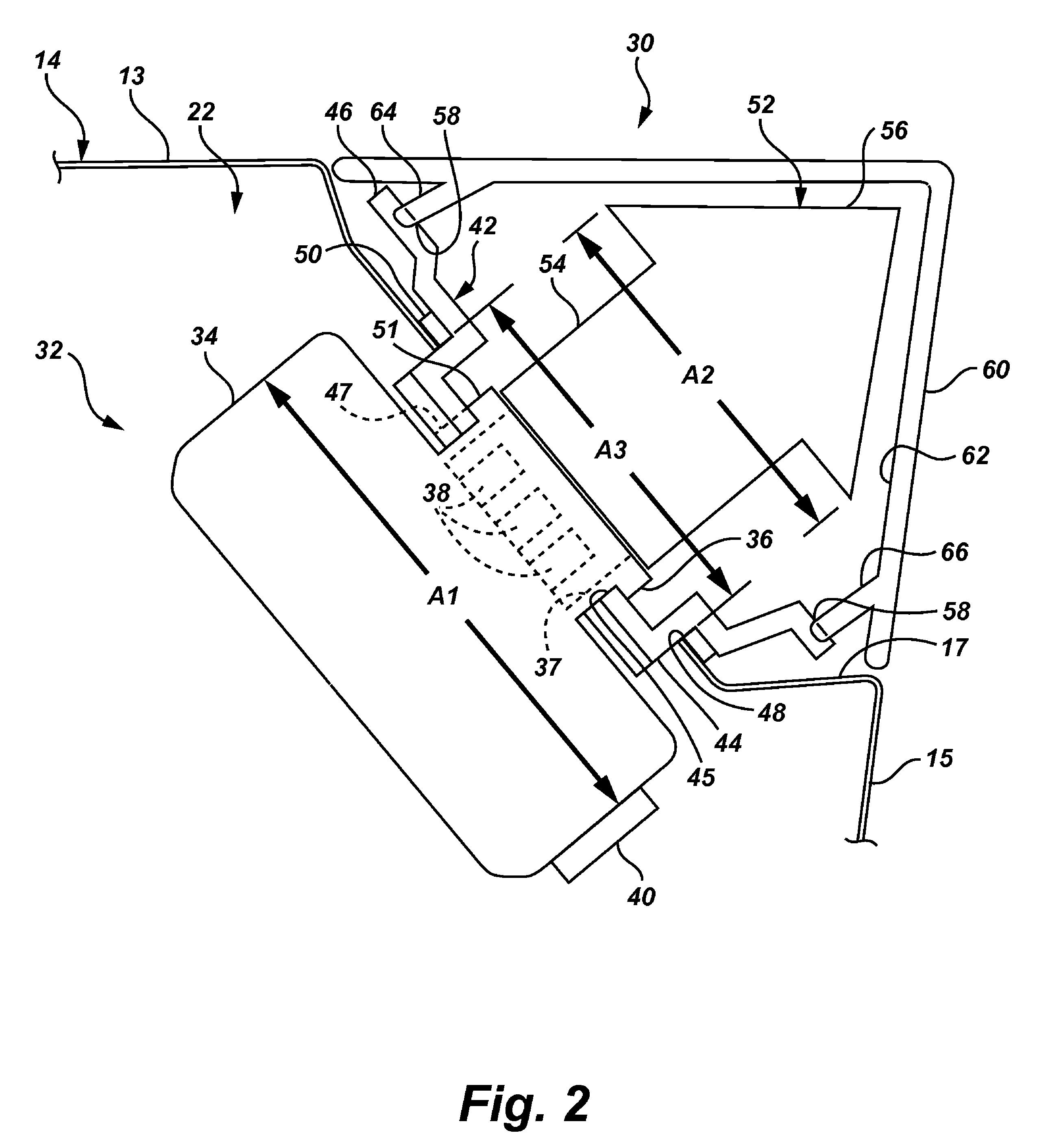
The present invention provides a variety of lamp assemblies for motorized vehicles that offer significant advantages over prior art lamp assemblies. These advantages include a simplified design that reduces the need for separate structure and components, cost savings, improved styling, and reduced labor and maintenance costs. The lamp assemblies offer a narrower and flatter design, and can be attached to the vehicle's exterior through an aperture in the vehicle's structure. The light source is a light emitting diode (LED) module that is attached to the vehicle's interior, and a light guide is used to transmit the light to the exterior of the vehicle. The light guide is designed to be attached to the vehicle's exterior, and the cross-sectional area of the aperture in the vehicle's structure is smaller than the cross-sectional area of the LED module and light guide. The lamp assemblies can be used in a variety of vehicles, such as automobiles, and the design offers significant advantages over traditional lamp assemblies.

Problems solved by technology

The lamp assemblies disclosed herein are also significantly smaller than traditional headlamp and tail lamp assemblies, freeing up otherwise scarce and valuable packaging space.

Method used


Image

  • Vehicle lamp assembly
  • Vehicle lamp assembly
  • Vehicle lamp assembly

Examples


Embodiment Construction

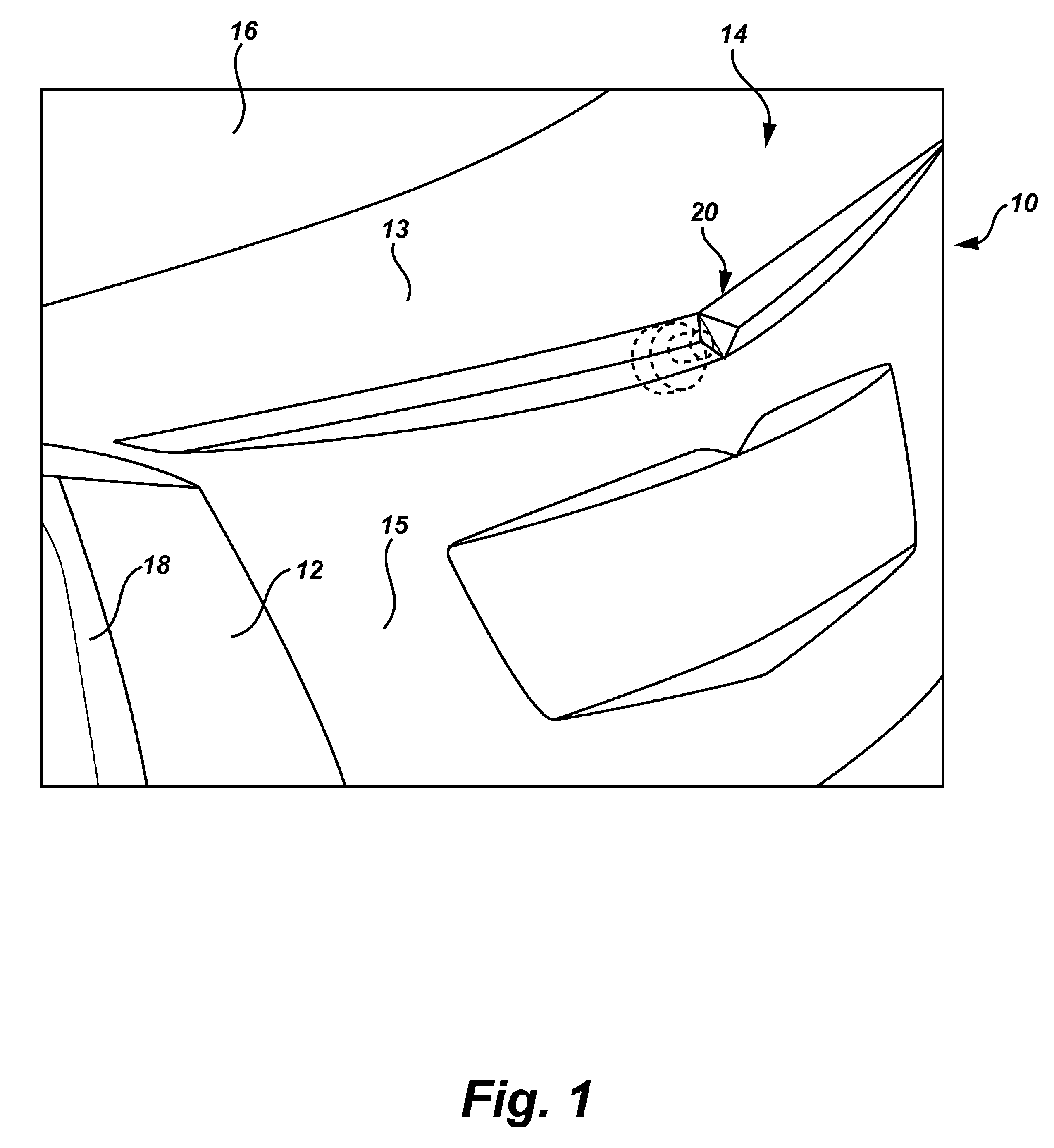
[0020]Referring to the drawings, wherein like reference numbers refer to like components throughout the several views, FIG. 1 is a perspective-view illustration of a representative motorized vehicle, identified generally as 10, with which the present invention may be incorporated and practiced. It should be readily understood that FIG. 1 is merely an exemplary application by which the present invention may be utilized. As such, the present invention is by no means limited to the vehicle configuration shown in FIG. 1. For instance, although the vehicle 10 is depicted in FIG. 1 as a standard passenger car, the present invention can be incorporated into any motorized vehicle platform, such as, but certainly not limited to, sport utility vehicles (SUVs), light trucks, heavy duty vehicles, minivans, conversion vans, buses, etc. Finally, the drawings presented herein are not to scale, and are provided purely for instructional purposes. Thus, the individual and relative dimensions and orie...


PUM


Abstract

The present invention provides various lamp assembly configurations for motorized vehicles. In one embodiment, the lamp assembly includes a light source, such as a light emitting diode (LED) module, that is operable to generate light. The light source is attached to the vehicle structure, located on the interior of the vehicle adjacent to the aperture. A light guide is operatively connected to the light source. The light guide is configured to transmit light generated by the light source to preselected locations along the exterior of the vehicle structure, and diffuse the light. The light guide is attached to the vehicle structure, located on the exterior of the vehicle adjacent to the aperture in opposing relation to the light source. The cross-sectional area of the aperture formed through the vehicle structure is less than the cross-sectional areas of the LED module body and the light emitting segment of the light guide.

Description

TECHNICAL FIELD[0001]The present invention relates generally to lamp assemblies for motorized vehicles. More specifically, this invention relates to arrangements for packaging lamp assemblies and attaching such lamp assemblies to the vehicle.BACKGROUND OF THE INVENTION[0002]Current production motorized vehicles, such as the modern-day automobile, are originally equipped with a lighting system to provide interior and exterior illumination for the vehicle operator. Such lighting systems include an array of lamp assemblies that are mounted or integrated to the front, sides and rear of the vehicle. The purpose of these lamp assemblies is to provide illumination for the driver to safely operate the vehicle in low-light conditions, such as nighttime driving, and to increase the conspicuity of the vehicle. Such lighting systems also display information about the vehicle's presence, position, size, direction of travel, as well as providing signaling functions to indicate the operator's inte...

Claims


Application Information

Patent Timeline
Patent Type & Authority Patents(United States)
IPC IPC(8): B60Q1/26
CPCB60Q1/0408B60Q1/302B60Q3/00F21S48/215F21S48/218B60Q1/2653F21S48/2268F21S48/2281B60Q1/2626B60Q1/2634F21S48/2237F21S43/14F21S43/15F21S43/237F21S43/245F21S43/249
Inventor SCHWAB, LEO F.ALLEN, ALFRED M.
Owner GM GLOBAL TECH OPERATIONS LLC
Learn More