
Complex optical lens apparatus for creating rectangular light output distribution

a complex optical lens and rectangular technology, applied in lighting and heating apparatus, discharge tube luminescnet screens, instruments, etc., can solve the problems of unmodified hemispherical emitters, unreliable and complex secondary optics, and high inefficiency of led light sources in meeting rectangular output, etc., to improve lens and overall product energy efficiency, improve reliability, and reduce operating temperature

Active Publication Date: 2011-04-12
TECNIQ
View PDF3 Cites 38 Cited by
  • Summary
  • Abstract
  • Description
  • Claims
  • Application Information

AI Technical Summary

Benefits of technology

[0014]It is a further object of the present invention to provide a higher efficiency and lower cost approach to the design of HAR rectangular output non-imaging optics.
[0015]It is yet a further object of the present invention to provide vehicle lights such as overland vehicle turn signals, stop lamps, identification lamps, side marker lamps and clearance lamps that are efficient and cost effective.
[0016]It is yet another object of the present invention to provide vehicle lights such as marine vessel navigation lighting such as bow lights, side lights, stern lights and steaming lights that are efficient and cost effective.
[0020]It is important to note that the present invention relates not only to the use of wide output LED sources in conjunction with an old style lens, but it also relates to the addition of a complex outer surface to the cylindrically shaped axially revolved lens for further light control necessary to generate wide output distributions. In practice, sources have a variety of output distributions which may or may not correspond to a pre-determined rectangular output distribution. The outer surface of the present invention is well suited to control the light energy on two orthogonal axes substantially independently and its combination with an axially revolved inner first surface results in significant control in the final output distribution. This results in an improvement in lens and overall product energy efficiency.
[0021]The optical efficiency improvement in the design of this improved LED-based product has several direct benefits including; increased reliability, lower operating temperature, reduced electrical requirements, greater product life and significantly reduced cost as compared to existing LED products. The resulting cost savings attendant with the implementation of the present invention makes high performance LED lamps more accessible to the general public and improves vehicle safety.

Problems solved by technology

The primary disadvantage of LED light sources is their cost.
Unfortunately, the nature of these lenses typically meant that complex secondary optics were required for use with the LED for redistributing the light into certain wide output regulated safety patterns.
However an unmodified hemispherical emitter is highly inefficient in meeting HAR rectangular output distribution as defined above.
LED devices with lenses incorporated therein have typically limited many of the devices to a narrow output pattern.
Unfortunately, the narrow output of the older LED sources and simple planar outer surfaces make this type of optic impractical for meeting evenly illuminating wider rectangular requirements.

Method used


Image

  • Complex optical lens apparatus for creating rectangular light output distribution
  • Complex optical lens apparatus for creating rectangular light output distribution
  • Complex optical lens apparatus for creating rectangular light output distribution

Examples


Embodiment Construction

[0059]The present invention relates to an improved rectangular light pattern generating method and devices and lenses made therefrom. The lenses and devices made in accordance with the method of the present invention have wide ranging uses in various applications including portable lamps and specialty lighting, over-land vehicles, watercraft, aircraft and manned spacecraft, automobiles, trucks, boats, ships, buses, vans, recreational vehicles, bicycles, motorcycles, mopeds, motorized cars, electric cars, airplanes, helicopters, space stations, shuttlecraft and the like.

[0060]The present invention provides an energy efficient and highly accurate method for distributing a wide output diffuse source of electromagnetic radiation (light) into a pre-determined rectangular requirement. Such wide output light distributions can be generated from nearly any source including but not limited to incandescent lamps, LED's, arc and gas discharge lamps.

[0061]In a typical application of the present ...


PUM


Abstract

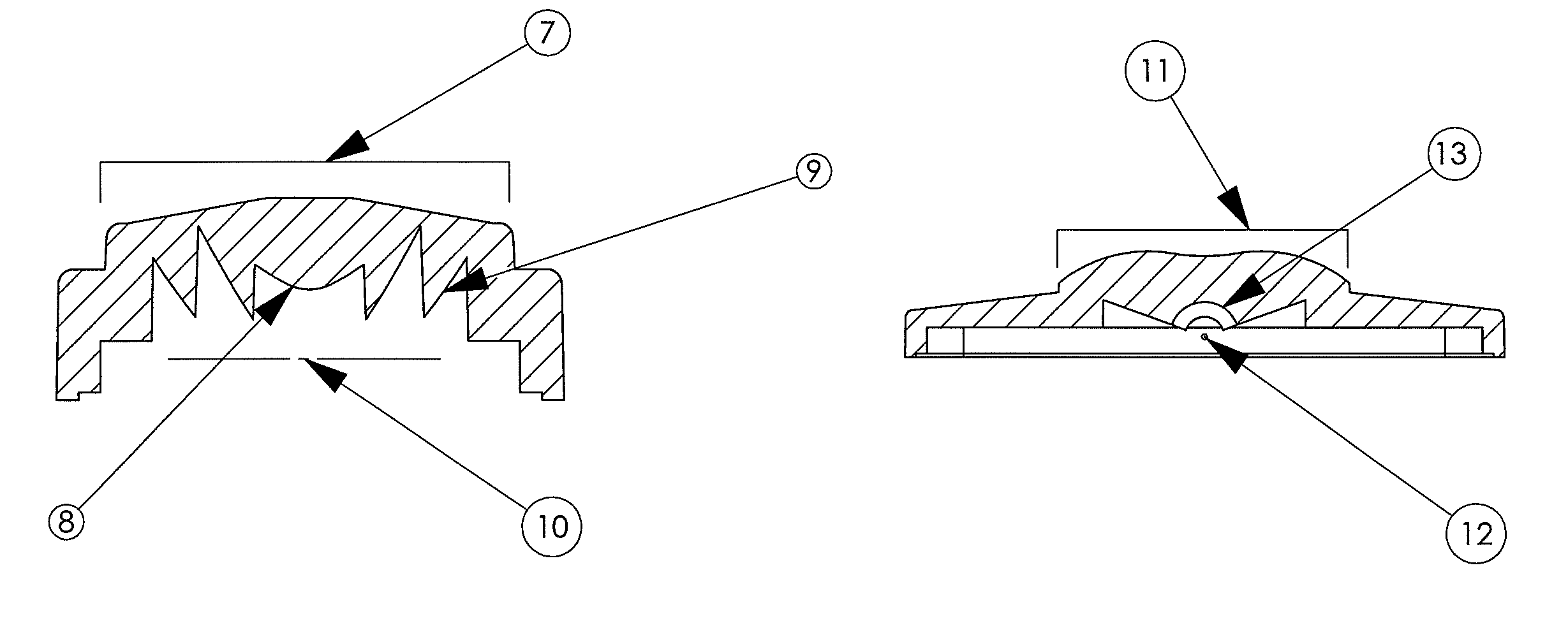
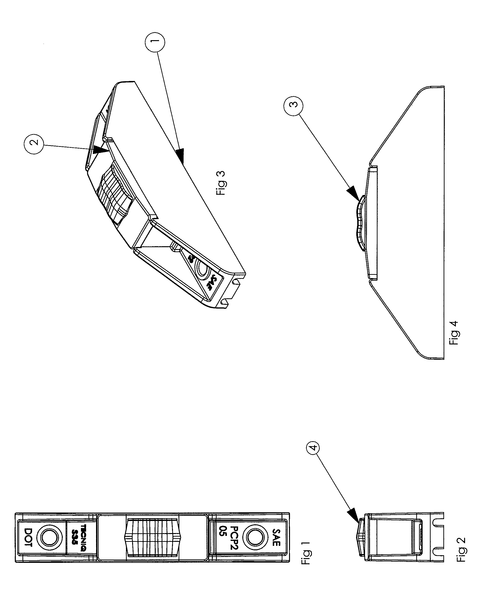
A device having an inner surface with a combination of reflective and refractive surface facets swept about an axis of revolution perpendicular to the optical axis of the device. The outer surface has a non-planar, non-circular, non-spherical shape. This outer surface generates an appropriate intensity distribution in a direction generally parallel to the major axis of the output rectangle and may also distribute energy generally parallelly to the minor axis of the output rectangle as well.

Description

CROSS-REFERENCE TO RELATED APPLICATION[0001]This application claims the benefit of U.S. Provisional Application Ser. No. 60 / 848,325, filed Sep. 29, 2006.FIELD OF THE INVENTION[0002]The present invention relates generally to the redistribution of radiant energy, particularly electromagnetic energy to achieve efficient and more cost effective products. More particularly, it relates to an apparatus and method for the efficient distribution of light energy from a conical wide-angle source into a high aspect ratio rectangular output pattern.BACKGROUND OF THE INVENTION[0003]There are many situations where electromagnetic energy is required to be distributed into a rectangular output. In the vast majority of these situations a high efficiency transfer of source energy is desirable. This is particularly true in regulated lighting. For example, overland vehicle safety lighting, aircraft lighting, street lamp lighting and marine lighting often require specific output patterns that are mandate...

Claims


Application Information

Patent Timeline
Patent Type & Authority Patents(United States)
IPC IPC(8): F21V3/02
CPCB60Q1/32B63B45/04F21V5/04G02B19/0061G02B19/0028F21V7/0091F21W2131/103F21Y2101/02F21Y2101/00F21Y2115/10
Inventor CONDON, PATRICK JEFFREYPRUSS, MARK BRYAN
Owner TECNIQ
Learn More